background image

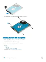
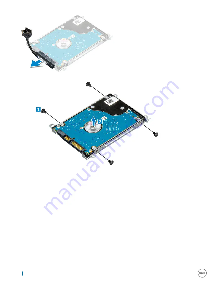
Then, remove the M3xL3 screws to detach the metal bracket from the HDD [1].

Installing the hard disk drive (HDD)

Tighten the M3xL3 screws that secure the metal bracket to the HDD

Connect the HDD cable interposer.

Insert the HDD into the connector on the computer.

Tighten the M2xL3 screws to secure the HDD to the computer.

Connect the HDD cable to the system board.

Install the:

a

battery

b

base cover

c

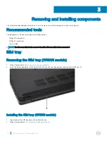
Installing the SIM tray (WWAN models)

Follow the procedure in 

After working inside your computer

.

22

Removing and installing components

Summary of Contents for Inspiron 3580

Page 1: ...Latitude 3480 Owner s Manual Regulatory Model P79G Regulatory Type P79G001 ...

Page 2: ...amage to hardware or loss of data and tells you how to avoid the problem WARNING A WARNING indicates a potential for property damage personal injury or death 2017 Dell Inc or its subsidiaries All rights reserved Dell EMC and other trademarks are trademarks of Dell Inc or its subsidiaries Other trademarks may be trademarks of their respective owners 2017 02 Rev A00 ...

Page 3: ...ttery 12 Installing the battery 13 Keyboard 13 Removing the keyboard 13 Installing the keyboard 17 WLAN Card 17 Removing the WLAN card 17 Installing the WLAN card 18 WWAN card 18 Removing the WWAN card 18 Installing the WWAN card 19 Memory Module 20 Removing the memory module 20 Installing the memory module 20 Hard disk drive HDD 21 Removing the hard disk drive HDD 21 Installing the hard disk driv...

Page 4: ...y options 32 Identifying the display adapter Windows 7 and Windows 10 32 Changing the screen resolution Windows 7 8 1 and 10 32 Adjusting brightness in Windows 10 32 Adjusting brightness in Windows 8 1 32 Adjusting brightness in Windows 7 32 Connecting to external display devices Windows 7 8 1 and 10 32 DDR4 33 Memory features 34 Verifying system memory 34 Hard drive options 34 Identifying the har...

Page 5: ...dating the BIOS in Windows 51 Updating BIOS on systems with bitlocker enabled 52 Updating your system BIOS using a USB flash drive 52 Updating the Dell BIOS in Linux and Ubuntu environments 52 System and setup password 53 Assigning a system password and setup password 53 Deleting or changing an existing system and or setup password 53 7 Software 55 Supported operating systems 55 Downloading driver...

Page 6: ... our Latitude Services and Support NOTE The Latitude 3488 model is offered only to customers in China Key Features 14 anti glare HD or FHD display Touchscreen option HD Webcam or IR camera on touch systems and dual array microphones Fingerprint reader option for added security and convenience Robust storage options including HDD Hybrid HDD and SSD Wide range of connectivity options wired Ethernet ...

Page 7: ...To avoid electrostatic discharge ground yourself by using a wrist grounding strap or by periodically touching an unpainted metal surface that is grounded to ground yourself before you touch the computer to perform any disassembly tasks CAUTION Handle components and cards with care Do not touch the components or contacts on a card Hold a card by its edges or by its metal mounting bracket Hold a com...

Page 8: ...ng system press and hold the power button for about 6 seconds to turn them off Before working inside your computer 1 Ensure that your work surface is flat and clean to prevent the computer cover from being scratched 2 Turn off your computer 3 If the computer is connected to a docking device docked undock it 4 Disconnect all network cables from the computer if available CAUTION If your computer has...

Page 9: ...esigned for other Dell computers 1 Replace the battery 2 Replace the base cover 3 Connect any external devices such as a port replicator or media base and replace any cards such as an ExpressCard 4 Connect any telephone or network cables to your computer CAUTION To connect a network cable first plug the cable into the network device and then plug it into the computer 5 Connect your computer and al...

Page 10: ...The 0 screw driver is for screws 0 1 and the 1 screw driver is for screws 2 4 SIM tray Removing the SIM tray WWAN models 1 Follow the procedure Before working inside your computer 2 Insert the tip of a paperclip into the hole of the SIM tray slot and then pull out and remove the SIM tray 1 Installing the SIM tray WWAN models 1 Align and push the SIM tray back into the SIM tray slot 2 Follow the pr...

Page 11: ...the base cover Removing the SIM tray WWAN models a Loosen the M2 5xL8 5 captive screws that secure the base cover to the computer 1 b Pry the base cover from the edge 2 NOTE You must use a plastic scribe to pry the base cover from the edge 2 4 Lift the base cover away from the computer Removing and installing components 11 ...

Page 12: ...els 5 Follow the procedure in After working inside your computer Battery Removing battery 1 Follow the procedure in Before working inside your computer 2 Remove the a Removing the SIM tray WWAN models b base cover 3 To remove the battery a Disconnect the battery cable from the connector on the system board 1 b Remove the M2 0x3 0 screws that secure the battery to the computer 2 c Lift the battery ...

Page 13: ...e computer 4 Install the a base cover b Installing the SIM tray WWAN models 5 Follow the procedure in After working inside your computer Keyboard Removing the keyboard 1 Follow the procedure in Before working inside your computer 2 Remove the a Removing the SIM tray WWAN models b base cover c battery 3 Gently pry out the keyboard using a plastic scribe Removing and installing components 13 ...

Page 14: ...4 Pry out the lower edge of the keyboard 1 and flip it over 2 14 Removing and installing components ...

Page 15: ...5 Then disconnect the backlight connector 1 and the keyboard connector 2 NOTE Disconnect backlight connector only if it is available in the system as it is optional Removing and installing components 15 ...

Page 16: ...6 Remove the keyboard away from the computer 16 Removing and installing components ...

Page 17: ...ps back into place 3 Install the a battery b base cover c Installing the SIM tray WWAN models 4 Follow the procedure in After working inside your computer WLAN Card Removing the WLAN card 1 Follow the procedure in Before working inside your computer 2 Remove the a Removing the SIM tray WWAN models b base cover c battery 3 To remove the WLAN card Removing and installing components 17 ...

Page 18: ...rt the WLAN card into its connector on the system board 2 Connect the two antenna cables to the WLAN card 3 Replace the metal bracket on the WLAN 4 Tighten the M2xL3 screw to secure the WLAN card and bracket to the system board 5 Install the a battery b base cover c Installing the SIM tray WWAN models 6 Follow the procedure in After working inside your computer WWAN card Removing the WWAN card 1 F...

Page 19: ... WWAN card from its connector on the system board 4 Installing the WWAN card 1 Insert the WWAN card into its connector on the system board 2 Connect the two antenna cables to the WWAN card 3 Replace the metal bracket on the WWAN 4 Tighten the M2xL3 screw to secure the WWAN card and bracket to the system board 5 Reconnect the battery 6 Install the a base cover b Installing the SIM tray WWAN models ...

Page 20: ... memory module latches 1 b Lift and remove the memory module from the system board 2 Installing the memory module 1 Insert the memory module into its connector on the system board 2 Gently push the memory module until the latches snap it into place 3 Install the a battery b base cover c Installing the SIM tray WWAN models 4 Follow the procedure in After working inside your computer 20 Removing and...

Page 21: ...2 Remove the a Removing the SIM tray WWAN models b base cover c battery 3 To remove the HDD a Disconnect the HDD cable from the system board 1 b Remove the M2xL3 screws that secure the HDD to the palmrest 2 c Lift the HDD from the computer 3 4 Disconnect the HDD cable interposer Removing and installing components 21 ...

Page 22: ...he HDD 2 Connect the HDD cable interposer 3 Insert the HDD into the connector on the computer 4 Tighten the M2xL3 screws to secure the HDD to the computer 5 Connect the HDD cable to the system board 6 Install the a battery b base cover c Installing the SIM tray WWAN models 7 Follow the procedure in After working inside your computer 22 Removing and installing components ...

Page 23: ...specifications Keyboard specifications Touchpad specifications Battery specifications AC adapter specifications Physical specifications Environmental specifications System specifications Feature Specification Chipset Intel Skylake and Kabylake integrated with processor DRAM bus width 64 bit Flash EPROM SPI 128 Mbits PCIe bus 100 MHz External Bus Frequency PCIe Gen3 8 GT s Processor specifications ...

Page 24: ...ication Memory connector Two SODIMM slots Memory capacity 16 GB 1 X 4 GB 1 x 8 GB 2 x 4 GB 1 x 16 GB 2 x 8 GB Memory type DDR4 SDRAM Speed 2133 MHz Minimum memory 4 GB Maximum memory 16 GB NOTE The actual memory speed is 2133 MHz but the label may read as 2400 MHz Hard drive options This laptop supports 128GB M 2 2280 SSD via carrier 256GB M 2 2280 SSD via carrier 32GB M 2 2242 SSD in WWAN slot 64...

Page 25: ...ky Lake Intel HD Graphics 520 Kaby Lake Intel HD Graphics 610 620 Discrete AMD Radeon R5 M430 External display support VGA HDMI 1 4 Camera specifications NOTE There are two camera options available HD Webcam and Infra red Camera The HD Webcam is available with non touch configuration and Infra red Camera is available with touch configuration The Infra red is the only camera that supports Window He...

Page 26: ...11e for AT T Verizon and Sprint USA not available with Skylake CPUs or Kabylake CEL CPU Qualcomm Snapdragon X7 LTE A DW5811e EMEA APJ ROW not available with Skylake CPUs or Kabylake CEL CPU Qualcomm Snapdragon X7 HSPA DW5811e China Indonesia India not available with Skylake CPUs or Kabylake CEL CPU Ports and connectors specifications Feature Specification Audio Stereo headset mic combo Video One 1...

Page 27: ...0 Hz Horizontal viewing angle HD 40 40 degrees FHD 80 80 degrees HD 40 40 degrees Vertical viewing angle HD 10 30 degrees FHD 80 80 degrees HD 10 30 degrees Pixel Pitch HD 0 226 mm FHD 0 161 mm HD 0 226 mm Power Consumption max HD 3 0W FHD 4 2W HD 3 0W Keyboard specifications Feature Specification Number of keys United States 80 keys United Kingdom 81 keys Europe and Brazil 82 keys Japan 84 keys T...

Page 28: ...idth 90 73mm 3 572 Weight 250 00 g Height 5 9mm 0 232 Voltage 15 2VDC Operating Charge 0 C to 50 C 32 F to 122 F Discharge 0 C to 70 C 32 F to 158 F Non operating 20 C to 65 C 4 F to 149 F Coin cell battery 3 V CR2032 lithium coin cell Life span 300 discharge per charge cycles AC adapter specifications Feature Specification Type 65 W E4 adapter 7 4 mm barrel 65 W E5 Rugged adapter 7 4 mm barrel av...

Page 29: ...weight and shipping weight is based on a typical configuration and may vary based on the actual configuration Environmental specifications Temperature Specifications Operating 0 C to 35 C 32 F to 95 F Storage 40 C to 65 C 40 F to 149 F Relative humidity maximum Specifications Operating 10 to 90 non condensing Storage 5 to 95 non condensing Altitude maximum Specifications Operating 0 m to 3048 m 0 ...

Page 30: ...ctors and power strips vary among countries Using an incompatible cable or improperly connecting the cable to the power strip or electrical outlet may cause fire or equipment damage Processors This laptop is shipped with the following 6th and 7th Generation Intel processors 6th Generation Intel Processors Intel Core i3 6006U Dual Core 3M cache 2 0GHz 15W Intel Core i5 6200U Dual Core 3M cache 2 3G...

Page 31: ...l Kabylake series chipset Identifying the chipset in Device Manager on Windows 10 1 Click inside the Cortana Search Box and type Control Panel and then click or press Enter on the keyboard for the appropriate search result 2 From the Control Panel select Device Manager 3 Expand System Devices and search for the chipset Identifying chipset in Device Manager on Windows 8 1 1 Click Settings on the Wi...

Page 32: ...able automatic screen brightness adjustment 1 Swipe in from the right edge of the display to access the Charms menu 2 Tap or click Settings Change PC Settings PC and devices Power and sleep 3 Use the Adjust my screen brightness automatically slider to enable or disable automatic brightness adjustment Adjusting brightness in Windows 7 To enable or disable automatic screen brightness adjustment 1 Cl...

Page 33: ...by without needing to refresh its memory Deep power down mode is expected to reduce standby power consumption by 40 to 50 percent DDR4 Details There are subtle differences between DDR3 and DDR4 memory modules as listed below Key notch difference The key notch on a DDR4 module is in a different location from the key notch on a DDR3 module Both notches are on the insertion edge but the notch locatio...

Page 34: ... minimum memory of 4 GB DDR4 2400 MHz running at 2133 MHz and a maximum memory of 16 GB 2400 MHz running at 2133 MHz Verifying system memory Windows 10 1 Tap the Windows button and select All Settings System 2 Under System tap About Windows 8 1 1 From your desktop start the Charms Bar 2 Select Control Panel and then select System Windows 7 Click Start Control Panel System Hard drive options This l...

Page 35: ...tart Control Panel Device Manager The hard drive is listed under Disk drives 2 Expand Disk drives Identifying the hard drive in the BIOS 1 Turn on or restart your system 2 When the Dell logo appears perform one of the following actions to enter the BIOS setup program With keyboard Tap F2 until the Entering BIOS setup message appears To enter the Boot selection menu tap F12 The hard drive is listed...

Page 36: ...0 compatibility New connectors and cable The topics below cover some of the most commonly asked questions regarding USB 3 0 USB 3 1 Gen 1 Speed Currently there are 3 speed modes defined by the latest USB 3 0 USB 3 1 Gen 1 specification They are Super Speed Hi Speed and Full Speed The new SuperSpeed mode has a transfer rate of 4 8Gbps While the specification retains Hi Speed and Full Speed USB mode...

Page 37: ...previously weren t USB territory like external RAID storage systems Listed below are some of the available SuperSpeed USB 3 0 USB 3 1 Gen 1 products External Desktop USB 3 0 USB 3 1 Gen 1 Hard Drives Portable USB 3 0 USB 3 1 Gen 1 Hard Drives USB 3 0 USB 3 1 Gen 1 Drive Docks Adapters USB 3 0 USB 3 1 Gen 1 Flash Drives Readers USB 3 0 USB 3 1 Gen 1 Solid state Drives USB 3 0 USB 3 1 Gen 1 RAIDs Op...

Page 38: ...eam to a surround audio system eliminating the need for a separate audio cable 3D Defines input output protocols for major 3D video formats paving the way for true 3D gaming and 3D home theater applications Content Type Real time signaling of content types between display and source devices enabling a TV to optimize picture settings based on content type Additional Color Spaces Adds support for ad...

Page 39: ... tap the Skype software that is shipped with the laptop the camera turns on Similarly if you are chatting on the internet and the application requests to access the webcam the webcam turns on Starting the camera application 1 Tap or click the Windows button and select All apps 2 Select Camera from the apps list 3 If the Camera App is not available in the apps list search for it Technology and comp...

Page 40: ...40 Technology and components ...

Page 41: ... Verifying system memory in system setup BIOS Updating the BIOS in Windows System and setup password Boot Sequence Boot Sequence allows you to bypass the System Setup defined boot device order and boot directly to a specific device for example optical drive or hard drive During the Power on Self Test POST when the Dell logo appears you can Access System Setup by pressing F2 key Bring up the one ti...

Page 42: ...ser password Read the current amount of memory or set the type of hard drive installed Before you use System Setup it is recommended that you write down the System Setup screen information for future reference CAUTION Unless you are an expert computer user do not change the settings for this program Certain changes can cause your computer to work incorrectly Accessing System Setup 1 Turn on or res...

Page 43: ... Legacy Option ROMs is disabled Enable Attempt Legacy Boot is enabled by default UEFI boot path security Always except internal HDD Default Always Never Date Time Allows you to change the date and time System Configuration screen options Option Description Integrated NIC Controls the on board LAN controller Enabled w PXe by default SATA Operation Allows you to configure the operating mode of the i...

Page 44: ...abled default Miscellaneous Devices Allows you to enable or disable the following devices Camera default enable Secure Digital SD card enabled Secure Digital SD card read only mode Hard drive Free Fall Protection enabled Secure Digital SD Boot enabled Video screen options Option Description LCD Brightness Allows you to set the display brightness depending up on the power source On Battery and On A...

Page 45: ...disable permission to the System and Hard Drive passwords when the admin password is set Default setting Allow Non Admin Password Changes is selected Non Admin Setup Changes Allows you to determine whether changes to the setup options are allowed when an Administrator Password is set If disabled the setup options are locked by the admin password Option allow wireless switch changes is not selected...

Page 46: ...e PK enabled by default KEK db dbx If you enable the Custom Mode the relevant options for PK KEK db and dbx appear The options are Save to File Saves the key to a user selected file Replace from File Replaces the current key with a key from a user selected file Append from File Adds a key to the current database from a user selected file Delete Deletes the selected key Reset All Keys Resets to def...

Page 47: ...ior Allows you to enable or disable the computer from turning on automatically when an AC adapter is connected Default setting Wake on AC is not selected Auto On Time Allows you to set the time at which the computer must turn on automatically The options are Disabled Every Day Weekdays Select Days Default setting Disabled USB Wake Support Allows you to enable USB devices to wake the system from St...

Page 48: ...ttery at a standard rate ExpressCharge The battery charges over a shorter time using Dell s fast charging technology This option is enabled by default Primarily AC use Custom If Custom Charge is selected you can also configure Custom Charge Start and Custom Charge Stop NOTE All charging mode may not be available for all the batteries To enable this option disable the Advanced Battery Charge Config...

Page 49: ...ss devices can be controlled by the Wireless Switch WWAN enabled by default WLAN enabled by default Bluetooth enabled by default Wireless Device Enable Allows you to enable or disable the internal wireless devices WLAN enabled by default Bluetooth All the options are enabled by default Maintenance screen options Option Description Service Tag Displays the Service Tag of your computer Asset Tag All...

Page 50: ... option controls the automatic boot flow for SupportAssist System Resolution Console and for Dell OS Recovery Tool OFF 1 2 default 3 Real Time Clock RTC reset The Real Time Clock RTC reset function allows you or your service technician to recover late model Dell Latitude and Precision systems from select No POST No Boot No Power situations You can initiate the RTC reset on the system from a power ...

Page 51: ...computer 2 Go to Dell com support Enter the Service Tag or Express Service Code and click Submit ClickDetect Product and follow the instructions on screen 3 If you are unable to detect or find the Service Tag click the Choose from all products 4 Choose the Products category from the list NOTE Choose the appropriate category to reach the product page 5 Select your computer model and the Product Sup...

Page 52: ... article for further details http www dell com support article us en 19 SLN143196 how to create a bootable usb flash drive using dell diagnostic deployment package dddp lang EN 1 Download the BIOS update EXE file to another system 2 Copy the file e g O9010A12 EXE onto the bootable USB Flash drive 3 Insert the USB Flash drive into the system that requires the BIOS update 4 Restart the system and pr...

Page 53: ...ase letters are not allowed Only the following special characters are allowed space 3 Type the system password that you entered earlier in the Confirm new password field and click OK 4 Press Esc and a message prompts you to save the changes 5 Press Y to save the changes The computer reboots Deleting or changing an existing system and or setup password Ensure that the Password Status is Unlocked in...

Page 54: ...The computer reboots 54 System setup options ...

Page 55: ...ows 7 32 64 bit Windows 8 1 64 bit China only Ubuntu Neokylin Yes OS Media Support Dell com support to download eligible Windows OS USB media available for upsell Downloading drivers 1 Turn on the laptop 2 Go to Dell com support 3 Click Product Support enter the Service Tag of your laptop and then click Submit NOTE If you do not have the Service Tag use the auto detect feature or manually browse f...

Page 56: ...nd Chipset and select your chipset driver 7 Click Download File to download the latest version of the chipset driver for your laptop 8 After the download is complete navigate to the folder where you saved the driver file 9 Double click the chipset driver file icon and follow the instructions on the screen Intel chipset drivers Verify if the Intel chipset drivers are already installed in the laptop...

Page 57: ...h an IR camera verify if the IR Camera driver is already installed in the system by referring to the illustration below There is no visible change in this entry Table 11 IR camera Before installation After installation NEXT Biometrics Fingerprint Reader For models with a fingerprint reader verify if the NEXT Biometrics fingerprint reader driver is already installed in the system by referring to th...

Page 58: ... for specific devices require user interaction Always ensure that you are present at the computer terminal when the diagnostic tests are performed Running the ePSA diagnostics 1 Power on the computer 2 As the computer boots press the F12 key as the Dell logo appears 3 On the boot menu screen select the Diagnostics option The Enhanced Pre boot System Assessment window is displayed 4 Click the arrow...

Page 59: ...he power button for 25 seconds The system RTC reset occurs after you release the power button NOTE If AC power is disconnected from the system during the process or the power button is held longer than 40 seconds the RTC reset process is aborted The RTC reset will reset the BIOS to Defaults un provision Intel vPro and reset the system date and time The following items are unaffected by the RTC res...

Page 60: ... service options Availability varies by country and product and some services may not be available in your area To contact Dell for sales technical support or customer service issues 1 Go to Dell com support 2 Select your support category 3 Verify your country or region in the Choose a Country Region drop down list at the bottom of the page 4 Select the appropriate service or support link based on...

Reviews: