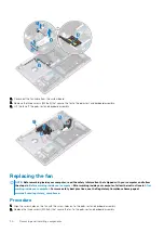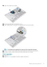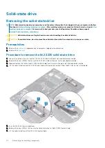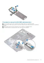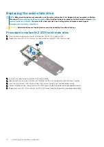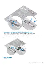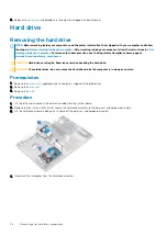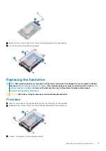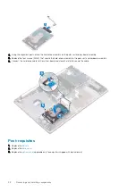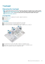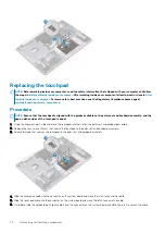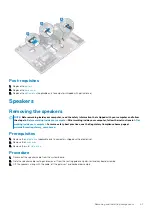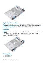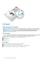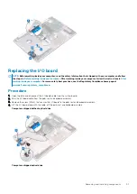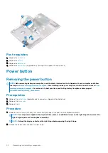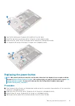
Procedure
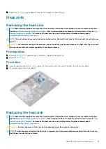
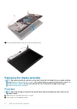
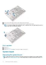
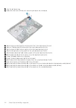
1. Place the heat sink on the system board and align the screw holes on the heat sink with the screw holes on the system board.
2. In sequential order (1->2->3->4) as indicated on the heat sink, tighten the captive screws to secure the heat sink to the system board.
Post-requisites
1. Replace the
.
2. Replace the
(applicable only to computers shipped with optical drive).
Display assembly
Removing the display assembly
NOTE:
Before working inside your computer, read the safety information that shipped with your computer and follow
the steps in
Before working inside your computer
. After working inside your computer, follow the instructions in
. For more safety best practices, see the Regulatory Compliance home page at
www.dell.com/regulatory_compliance
Prerequisites
1. Remove the
(applicable only to computers shipped with optical drive).
2. Remove the
3. Remove the
.
Procedure
NOTE:
Steps 1 to 3 are applicable only for the computers that are shipped with optical drive.
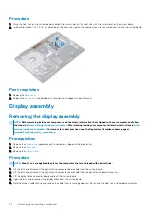
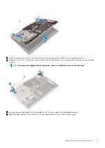
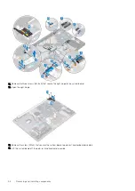
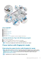
1. Lift the latch and disconnect the optical-drive connector-board cable from the system board.
2. Lift the latch and disconnect the optical-drive connector-board cable from the optical-drive board connector.
3. Lift the optical-drive connector-board cable off the system board.
4. Open the latch and disconnect the display cable from the system board.
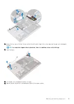
5. Note the display-cable routing and remove the cable from its routing guides on the fan and the palm-rest and keyboard assembly.
44
Removing and installing components

