
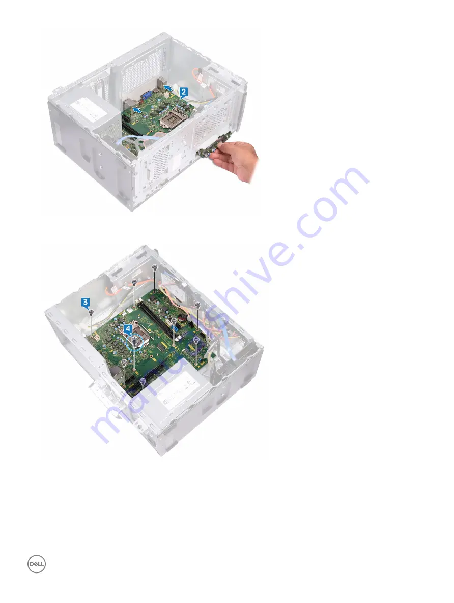
3
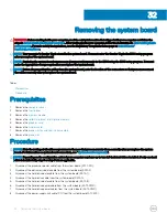
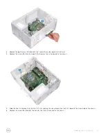
Replace the eight screws (#6-32x6.35) that secure the system board to the chassis.
4
Replace the screw (#6-32x4.8, standoff) that secures the system board to the chassis.
5
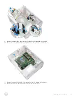
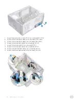
Slide the front-I/O bracket into the front-I/O slot, aligning the screw hole on the front-I/O board to the screw hole on the chassis.
6
Replace the screw (#6-32x6.35) that secures the front-I/O bracket to the chassis.
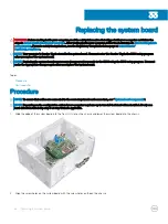
Replacing the system board
57
Summary of Contents for Inspiron 3670
Page 15: ...Removing the front bezel 15 ...
Page 17: ...Post requisites Replace the computer cover Replacing the front bezel 17 ...
Page 19: ...Removing the memory module 19 ...
Page 21: ...Post requisites Replace the computer cover Replacing the memory module 21 ...
Page 23: ...Removing the solid state drive Intel Optane 23 ...
Page 30: ...30 Removing the wireless card ...
Page 35: ...Post requisites Replace the computer cover Replacing the optical drive 35 ...
Page 47: ...Removing the 2 5 inch hard drive 47 ...
Page 55: ...Removing the system board 55 ...
Page 72: ...Post requisites Replace the computer cover 72 System and setup password ...


