background image

About this task

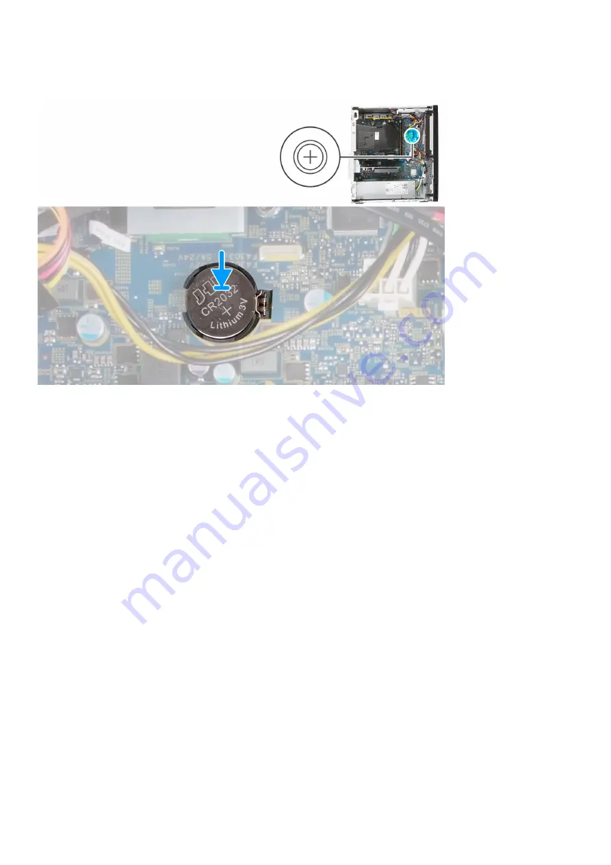
The following image(s) indicate the location of the coin-cell battery and provides a visual representation of the installation procedure.

Steps

1. Insert the coin-cell battery into its slot on the system board with the positive side (+) label facing up.
2. Press down and and snap the coin-cell battery into the slot on the system board.

Next steps

1. Install the 

left-side cover

.

2. Follow the procedure in 

After working inside your computer

.

Wireless card

Removing the wireless card

Prerequisites

1. Follow the procedure in 

Before working inside your computer

.

2. Remove the 

left-side cover

.

About this task

The following image(s) indicate the location of the wireless card and provides a visual representation of the removal procedure.

Removing and installing components

19

Summary of Contents for Inspiron 3880

Page 1: ...Inspiron 3880 Service Manual Regulatory Model D29M Regulatory Type D29M002 April 2020 Rev A00 ...

Page 2: ...ential damage to hardware or loss of data and tells you how to avoid the problem WARNING A WARNING indicates a potential for property damage personal injury or death 2020 Dell Inc or its subsidiaries All rights reserved Dell EMC and other trademarks are trademarks of Dell Inc or its subsidiaries Other trademarks may be trademarks of their respective owners ...

Page 3: ... memory modules 13 Installing the memory modules 14 Solid state drive Intel Optane 15 Removing the solid state drive Intel Optane 15 Installing the SSDIntelOptane 16 Coin cell battery 18 Removing the coin cell battery 18 Installing the coin cell battery 18 Wireless card 19 Removing the wireless card 19 Installing the wireless card 20 Graphics card 22 Removing the graphics card 22 Installing the gr...

Page 4: ...S overview 48 Entering BIOS setup program 48 Navigation keys 48 Boot Sequence 48 System setup options 49 Flashing the BIOS 53 System and setup password 53 Assigning a system setup password 54 Deleting or changing an existing system setup password 54 Clearing CMOS settings RTC reset 55 Clearing BIOS System Setup and System passwords 55 5 Troubleshooting 56 Real Time Clock RTC Reset 56 System diagno...

Page 5: ...onnect your computer from all power sources before opening the computer cover or panels After you finish working inside the computer replace all covers panels and screws before connecting your computer to an electrical outlet CAUTION To avoid damaging the computer ensure that the work surface is flat dry and clean CAUTION To avoid damaging the components and cards handle them by their edges and av...

Page 6: ...e anti static packing material until you are ready to install the component Before unwrapping the anti static packaging ensure that you discharge static electricity from your body Before transporting a static sensitive component place it in an anti static container or packaging ESD field service kit The unmonitored Field Service kit is the most commonly used service kit Each Field Service kit incl...

Page 7: ...sport ESD protection summary It is recommended that all field service technicians use the traditional wired ESD grounding wrist strap and protective anti static mat at all times when servicing Dell products In addition it is critical that technicians keep sensitive parts separate from all insulator parts while performing service and that they use anti static bags for transporting sensitive compone...

Page 8: ...ed when the component is replaced NOTE Some computers have magnetic surfaces Ensure that the screws are not left attached to such surface when replacing a component NOTE Screw color may vary with the configuration ordered Table 1 Screw list Component Secured to Screw type Quantity Screw image Left side cover Chassis 6 32 2 Solid state drive System board M2x3 1 Wireless card System board M2x3 1 3 5...

Page 9: ... Screw image System board Chassis 6 32 M 2 card mounting screw 1 System board components Figure 1 System board components 1 power button cable connector PWR SW 2 media card reader board cable connector SD CARD 3 coin cell battery slot Removing and installing components 9 ...

Page 10: ... 11 M 2 2230 2280 card slot for solid state drive Intel Optane M 2 SSD PCIE2 12 processor slot 13 processor power cable connector ATX CPU 14 fan cable connector FAN SYS Left side cover Removing the left side cover Prerequisites 1 Follow the procedure in Before working inside your computer About this task The following image s indicate the location of the left side cover and provides a visual repre...

Page 11: ...g component before performing the installation process About this task The following image s indicate the location of the left side cover and provides a visual representation of the installation procedure Steps 1 Align the tabs on the left side cover with the slots on the chassis and slide it towards the front of the computer 2 Replace the two thumb screws 6 32 that secure the left side cover to t...

Page 12: ...al representation of the removal procedure Steps 1 Place the computer in an upright position 2 Gently pry and release the front cover tabs sequentially from the top 3 Rotate the front cover outward from the chassis 4 Remove the front cover from the chassis Installing the front cover Prerequisites If you are replacing a component remove the existing component before performing the installation proc...

Page 13: ...sert the front cover tabs with the slots on the chassis 3 Rotate the front cover towards the chassis and snap it into place Next steps 1 Install the left side cover 2 Follow the procedure in After working inside your computer Memory modules Removing the memory modules Prerequisites 1 Follow the procedure in Before working inside your computer 2 Remove the left side cover Removing and installing co...

Page 14: ...to step 3 to remove any other memory modules installed in your computer NOTE Note the slot and the orientation of the memory module in order to install the replacement in the correct slot NOTE If the memory module is difficult to remove gently ease the memory module back and forth to remove it from the slot Installing the memory modules Prerequisites If you are replacing a component remove the exi...

Page 15: ...stall it NOTE Repeat step 1 to step 3 when installing more than one memory module in your computer Next steps 1 Install the left side cover 2 Follow the procedure in After working inside your computer Solid state drive Intel Optane Removing the solid state drive Intel Optane Prerequisites 1 Follow the procedure in Before working inside your computer 2 Remove the left side cover About this task NOT...

Page 16: ...hat secures the solid state drive Intel Optane to the system board 3 Slide and lift the solid state drive Intel Optane from the M 2 card slot on the system board Installing the SSDIntelOptane Prerequisites If you are replacing a component remove the existing component before performing the installation process About this task NOTE You may install the following supported modules on your computer s ...

Page 17: ...ch on the solid state drive Intel Optane 2 Align the notch on the solid state drive Intel Optane with the tab on the M 2 card slot 3 Slide the solid state drive Intel Optane into the M 2 card slot on the system board 4 Replace the screw M2x3 that secures the solid state drive Intel Optane to the system board Next steps 1 Install the left side cover 2 Follow the procedure in After working inside yo...

Page 18: ...figuration error message is displayed prompting you to enter the BIOS and configure the date and time The computer starts functioning normally after setting the date and time The following image s indicate the location of the coin cell battery and provides a visual representation of the removal procedure Steps 1 Lay the computer with its right side facing down 2 Using your finger push the coin cel...

Page 19: ...ap the coin cell battery into the slot on the system board Next steps 1 Install the left side cover 2 Follow the procedure in After working inside your computer Wireless card Removing the wireless card Prerequisites 1 Follow the procedure in Before working inside your computer 2 Remove the left side cover About this task The following image s indicate the location of the wireless card and provides...

Page 20: ...om the wireless card 5 Slide and remove the wireless card at an angle from the wireless card slot Installing the wireless card Prerequisites If you are replacing a component remove the existing component before performing the installation process About this task The following image s indicate the location of the wireless card and provides a visual representation of the installation procedure 20 Re...

Page 21: ...angle White Auxiliary black triangle Black 2 Slide and place the wireless card bracket on the wireless card 3 Align the notch on the wireless card with the tab on the wireless card slot 4 Slide the wireless card at an angle into the wireless card slot 5 Replace the screw M2x3 that secures the wireless card to the system board Next steps 1 Install the left side cover 2 Follow the procedure in After...

Page 22: ...of the graphics card and provides a visual representation of the removal procedure Steps 1 Lay the computer with its right side facing down 2 Locate the graphics card installed in the PCIe x16 card slot 3 Lift the pull tab and open the expansion card door 4 Push and hold the securing tab on the graphics card slot and lift the graphics card from the PCIe x16 card slot 22 Removing and installing com...

Page 23: ...provides a visual representation of the installation procedure Steps 1 Align the graphics card with the PCIe x16 card slot on the system board 2 Using the alignment post connect the card in the connector and press down firmly Ensure that the card is firmly seated 3 Close the expansion card door Next steps 1 Install the left side cover 2 Follow the procedure in After working inside your computer Re...

Page 24: ...low the procedure in Before working inside your computer 2 Remove the left side cover About this task The following image s indicate the location of the power supply and provides a visual representation of the removal procedure 24 Removing and installing components ...

Page 25: ...ly power to the following components at the two location Processor System board 4 Remove the power supply cables from the routing guides on the chassis 5 Press down on the securing clip to release the power supply from the chassis 6 Slide and lift the power supply from its slot on the chassis Installing the power supply Prerequisites If you are replacing a component remove the existing component b...

Page 26: ...About this task The following image s indicate the location of the power supply and provides a visual representation of the installation procedure 26 Removing and installing components ...

Page 27: ...location Processor System board 4 Replace the three screws 6 32 that secure the power supply to the chassis Next steps 1 Install the left side cover 2 Follow the procedure in After working inside your computer Hard drive Removing the hard drive Prerequisites 1 Follow the procedure in Before working inside your computer 2 Remove the left side cover 3 Remove the front cover About this task The follo...

Page 28: ...r cable and hard drive data cable 3 Remove the five screws 6 32 that secure the hard drive to the chassis 4 Lift the hard drive off the chassis Installing the hard drive Prerequisites If you are replacing a component remove the existing component before performing the installation process About this task The following image s indicate the location of the hard drive and provides a visual representa...

Page 29: ...to the hard drive 3 Replace the four screws 6 32 that secure the hard drive to the chassis Next steps 1 Install the front cover 2 Install the left side cover 3 Follow the procedure in After working inside your computer Optical drive Removing the optical drive Prerequisites 1 Follow the procedure in Before working inside your computer 2 Remove the front cover Removing and installing components 29 ...

Page 30: ... with its right side facing down 2 Disconnect the optical drive power cable from the optical drive 3 Disconnect the optical drive data cable from the optical drive 4 Remove the two screws M2x2 that secure the optical drive to the chassis 5 Slide and lift the optical drive from its slot on the chassis Installing the optical drive Prerequisites If you are replacing a component remove the existing co...

Page 31: ... into its slot on the chassis 2 Align the screw holes on the optical drive with the screw holes on the chassis 3 Replace the two screws M2x2 that secure the optical drive to the chassis 4 Connect the optical drive power cable to the connector on the optical drive 5 Connect the optical drive data cable to the connector on the optical drive Next steps 1 Install the left side cover 2 Install the fron...

Page 32: ...n of the media card reader and provides a visual representation of the removal procedure Steps 1 Lay the computer with its right side facing down 2 Remove the screw 6 32 that secures the media card reader to the chassis 3 Using the tip of a Phillips head screw driver push on the screw hole location to release the media card reader 4 Slide and lift the media card reader from the slot on the chassis...

Page 33: ...ocation of the media card reader and provides a visual representation of the installation procedure Steps 1 Connect the media card reader into its slot on the chassis 2 Replace the screw 6 32 that secures the media card reader to the chassis Next steps 1 Install the front cover 2 Install the left side cover 3 Follow the procedure in After working inside your computer Removing and installing compon...

Page 34: ... following image s indicate the location of the fan shroud and provides a visual representation of the removal procedure Steps 1 Lay the computer with its right side facing down 2 Press on both securing clips to release the fan shroud from the fan and heat sink assembly 3 Slide and lift the fan shroud off the system board 34 Removing and installing components ...

Page 35: ... image s indicate the location of the fan shroud and provides a visual representation of the installation procedure Steps Place the fan shroud into place on the fan and heat sink assembly and snap it into place Next steps 1 Install the left side cover 2 Follow the procedure in After working inside your computer Fan and heat sink assembly Removing and installing components 35 ...

Page 36: ...fer areas on the heat sink The oils in your skin can reduce the heat transfer capability of the thermal grease The following image s indicate the location of the fan and heat sink assembly and provides a visual representation of the removal procedure Steps 1 Lay the computer with its right side facing down 2 Disconnect the fan cable from the system board 3 In a reverse sequential order 4 3 2 1 loo...

Page 37: ... fan and heat sink assembly and provides a visual representation of the installation procedure Steps 1 Gently place the fan and heat sink assembly on the processor 2 Align the screw holes on the fan and heat sink assembly with the screw holes on the system board 3 In sequential order 1 2 3 4 tighten the four captive screws that secure the fan and heat sink assembly to the system board 4 Connect th...

Page 38: ...become hot during normal operation Allow sufficient time for the heat sink to cool before you touch it CAUTION For maximum cooling of the processor do not touch the heat transfer areas on the heat sink The oils in your skin can reduce the heat transfer capability of the thermal grease The following image s indicate the location of the processor and provides a visual representation of the removal p...

Page 39: ...er 4 Gently lift the processor from the processor socket on the system board Installing the processor Prerequisites If you are replacing a component remove the existing component before performing the installation process About this task NOTE If either the processor or the fan and heat sink assembly is replaced use the thermal grease provided in the kit to ensure that thermal conductivity is achie...

Page 40: ...Remove the front cover 3 Remove the left side cover 4 Remove the fan shroud 5 Remove the solid state drive Intel Optane 6 Remove the coin cell battery 7 Remove the wireless card 8 Remove the hard drive 9 Remove the graphics card 10 Remove the media card reader 11 Remove the fan and heat sink assembly 12 Remove the processor About this task NOTE For computers shipped with 10th Generation Intel Core...

Page 41: ...Removing and installing components 41 ...

Page 42: ...42 Removing and installing components ...

Page 43: ...r 6 Disconnect the following cables from the system board power supply cables hard drive cable power button cable 7 Remove the M 2 card mounting screw 6 32 that secures the system board to the chassis NOTE The location of the M 2 card mounting screw will differ than what is shown in the image depending on the type of M 2 card installed in the slot on the system board 8 Remove the eight screws 6 32...

Page 44: ... processors a VGA connector cover is installed over the VGA connector and must be installed after the VGA connector board has been installed NOTE If either the processor or the fan and heat sink assembly is replaced use the thermal grease provided in the kit to ensure that thermal conductivity is achieved The following image s indicate the location of the system board and provides a visual represe...

Page 45: ...Removing and installing components 45 ...

Page 46: ...ly cables hard drive cable power button cable 5 Close the I O cover door 6 Replace the screw 6 32 that secures the I O cover door to the chassis 7 Place the VGA connector cover over the VGA connector if applicable 8 Tighten the two captive screws that secure the VGA connector cover to the VGA connector if applicable Next steps 1 Install the processor 2 Install the fan and heat sink assembly 3 Inst...

Page 47: ...rivers and downloads When troubleshooting downloading or installing drivers it is recommended that you read the Dell Knowledge Based article Drivers and Downloads FAQ SLN128938 3 Drivers and downloads 47 ...

Page 48: ...tup program About this task Turn on or restart your computer and press F2 immediately Navigation keys NOTE For most of the System Setup options changes that you make are recorded but do not take effect until you restart the system Keys Navigation Up arrow Moves to the previous field Down arrow Moves to the next field Enter Selects a value in the selected field if applicable or follow the link in t...

Page 49: ...s the express service code of the computer Memory Information Memory Installed Displays the total computer memory installed Memory Available Displays the total computer memory available Memory Speed Displays the memory speed Memory Channel Mode Displays single or dual channel mode Memory Technology Displays the technology used for the memory DIMM 1 Size Displays the DIMM 1 memory size DIMM 2 Size ...

Page 50: ...hen booting a UEFI boot path from the F12 boot menu Default Disabled Never Enable or disable the system to prompt the user to enter the Admin password when booting a UEFI boot path from the F12 boot menu Default Disabled Date Time Displays the current date in MM DD YY format and current time in HH MM SS AM PM format Table 4 System setup options System Configuration menu System Configuration Integr...

Page 51: ...ass for Clear Command Enable or disable the TPM Physical Presence Interface PPI When enabled this setting will allow the OS to skip BIOS PPI user prompts when issuing the Clear command Changes to this setting take effect immediately Default Disabled Absolute R Enable or disable the BIOS module interface of the optional Computrace R Service from Absolute Software Admin Setup Lockout Enable to preve...

Page 52: ... time This option can be configured only if the Auto On Time is set to Everyday Weekdays or Selected Days Default Disabled USB Wake Support Enable the USB devices to wake the computer from Standby Deep Sleep Control Enables you to control the Deep Sleep mode support Wake on LAN WLAN Enables the computer to be powered on by special LAN signals Block sleep Enables you to block entering to sleep mode...

Page 53: ...r SupportAssist System Resolution Console and for Dell OS Recovery tool Flashing the BIOS About this task You may need to flash update the BIOS when an update is available or when you replace the system board Follow these steps to flash the BIOS Steps 1 Turn on your computer 2 Go to www dell com support 3 Click Product support enter the Service Tag of your computer and then click Submit NOTE If yo...

Page 54: ...ve up to 32 characters The password can contain the numbers 0 through 9 Only lower case letters are valid upper case letters are not allowed Only the following special characters are allowed space 3 Type the system password that you entered earlier in the Confirm new password field and click OK 4 Press Esc and a message prompts you to save the changes 5 Press Y to save the changes The computer reb...

Page 55: ... as well as reset the Real Time Clock on your BIOS Steps 1 Press and hold the power button for 30 seconds 2 Release the power button and allow the system to boot Clearing BIOS System Setup and System passwords About this task NOTE To conduct a BIOS and System password reset you must call the Dell Tech Support number in your region Steps 1 Key in your computer s service tag number into the locked B...

Page 56: ...supply state Hard drive activity light Turns on when the computer reads from or writes to the hard drive Table 15 LED codes Diagnostic light codes Problem description 1 2 Unrecoverable SPI flash failure 2 1 CPU failure 2 2 System board failure corrupt BIOS ROM error 2 3 No memory RAM detected 2 4 Memory RAM failure 2 5 Invalid Memory installed 2 6 System board error chipset error clock failure gat...

Page 57: ...Dell THE FILE BEING COPIED IS TOO LARGE FOR THE DESTINATION DRIVE The file that you are trying to copy is too large to fit on the disk or the disk is full Try copying the file to a different disk or use a larger capacity disk A FILENAME CANNOT CONTAIN ANY OF THE FOLLOWING CHARACTERS Do not use these characters in filenames GATE A20 FAILURE A memory module may be loose Reinstall the memory module o...

Page 58: ...ck Key test in Dell Diagnostics LICENSED CONTENT IS NOT ACCESSIBLE IN MEDIADIRECT Dell MediaDirect cannot verify the Digital Rights Management DRM restrictions on the file so the file cannot be played MEMORY ADDRESS LINE FAILURE AT ADDRESS READ VALUE EXPECTING VALUE A memory module may be faulty or improperly seated Reinstall the memory module or if necessary replace it MEMORY ALLOCATION ERROR The...

Page 59: ... CLOCK STOPPED The reserve battery that supports the system configuration settings may require recharging Connect your computer to an electrical outlet to charge the battery If the problem persists Contact Dell TIME OF DAY NOT SET PLEASE RUN THE SYSTEM SETUP PROGRAM The time or date stored in the system setup program does not match the system clock Correct the settings for the Date and Time option...

Page 60: ...It consists of tools to diagnose and troubleshoot issues that may occur before your computer boots to the operating system It enables you to diagnose hardware issues repair your computer back up your files or restore your computer to its factory state You can also download it from the Dell Support website to troubleshoot and fix your computer when it fails to boot into their primary operating syst...

Page 61: ...wnload is complete navigate to the folder where you saved the BIOS update file 9 Double click the BIOS update file icon and follow the instructions on the screen WiFi power cycle About this task If your computer is unable to access the internet due to WiFi connectivity issues a WiFi power cycle procedure may be performed The following procedure provides the instructions on how to conduct a WiFi po...

Page 62: ...ne based support and service options Availability varies by country and product and some services may not be available in your area To contact Dell for sales technical support or customer service issues Steps 1 Go to Dell com support 2 Select your support category 3 Verify your country or region in the Choose a Country Region drop down list at the bottom of the page 4 Select the appropriate servic...

Reviews: