4
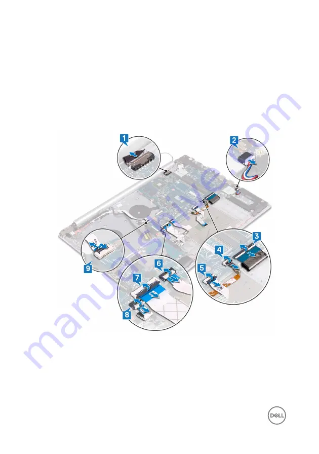
Open the latch and disconnect the keyboard back-light cable from the system
board.
5
Open the latch and disconnect the touchpad cable from the system board.
6
Open the latch and disconnect the hard-drive cable from the system board.
7
Open the latch and disconnect the I/O board cable from the system board.
8
Open the latch and disconnect the finger-print reader cable from the system
board.
9
Open the latch and disconnect the power-button board cable from the system
board.
10
Remove the three screws (M2.5x5) that secure the right hinge to the system
board.
90
Summary of Contents for Inspiron 5570
Page 28: ...6 Disconnect the battery cable from the system board 28 ...
Page 32: ...2 Lift the battery off the palm rest and keyboard assembly 32 ...
Page 46: ...2 Peel the coin cell battery cable from the palm rest and keyboard assembly 46 ...
Page 51: ...8 Lift the fan off the palm rest and keyboard board assembly 51 ...
Page 54: ...3 Slide and remove the solid state drive from the solid state drive slot 54 ...
Page 59: ...6 Lift the hard drive bracket off the hard drive 59 ...
Page 63: ...6 Slide and lift the touchpad off the palm rest and keyboard assembly 63 ...
Page 66: ...3 Lift the left speaker along with the cable off the palm rest and keyboard assembly 66 ...
Page 69: ...3 Lift the heat sink off the system board 69 ...
Page 72: ...6 Lift the power adapter port along with its cable off the palm rest and keyboard assembly 72 ...
Page 76: ...7 Open the hinges 8 Lift the palm rest and keyboard assembly at an angle 76 ...
Page 77: ...9 Slide and remove the palm rest and keyboard assembly off the display assembly 77 ...
Page 78: ...10 After performing all the above steps you are left with display assembly 78 ...
Page 83: ...4 Lift the I O board off the palm rest and keyboard assembly 83 ...
Page 87: ...6 Lift the power button board along with the cable off the palm rest and keyboard assembly 87 ...
Page 92: ...13 Lift the system board off the palm rest and keyboard assembly 92 ...
Page 103: ...2 Remove the display bezel off the display back cover and antenna assembly 103 ...
Page 106: ...3 Lift the camera module from the display back cover and antenna assembly 106 ...
Page 110: ...5 Lift the display panel away from the display back cover and antenna assembly 110 ...
Page 114: ...3 Lift the hinges and brackets off the display back cover and antenna assembly 114 ...
Page 117: ...3 Remove the display cable from the display back cover and antenna assembly 117 ...
Page 120: ...120 ...


