background image

Identifying the hard drive in BIOS setup program.................................................................................................. 77

USB features.....................................................................................................................................................................78

USB 3.0 (SuperSpeed USB)..................................................................................................................................... 78
Speed...........................................................................................................................................................................78
Applications.................................................................................................................................................................79
Compatibility............................................................................................................................................................... 79
Downloading the USB 3.0 driver..............................................................................................................................80

HDMI................................................................................................................................................................................. 80

Connecting to external display devices...................................................................................................................80

Wi-Fi.................................................................................................................................................................................. 80

Turning Wi-Fi on or off.............................................................................................................................................. 80
Configuring Wi-Fi........................................................................................................................................................81
Downloading the Wi-Fi driver....................................................................................................................................81

Camera...............................................................................................................................................................................81

Identifying the webcam in device manager.............................................................................................................81
Starting the camera application............................................................................................................................... 82

Memory features..............................................................................................................................................................82

Verifying system memory in Windows 10 and Windows 7 ...................................................................................82
Verifying system memory in setup...........................................................................................................................82
DDR4........................................................................................................................................................................... 83
Testing memory using ePSA.....................................................................................................................................84

Media-card reader........................................................................................................................................................... 84

Downloading the media-card reader driver............................................................................................................ 84

Realtek HD audio drivers.................................................................................................................................................84

Downloading the audio driver...................................................................................................................................85

Operating System............................................................................................................................................................ 85
Service tag location......................................................................................................................................................... 85

4 System setup............................................................................................................................................... 87

BIOS Overview................................................................................................................................................................. 87

Boot menu...................................................................................................................................................................87
Navigation Keys..........................................................................................................................................................87
Updating the BIOS in Windows ...............................................................................................................................88

System setup options......................................................................................................................................................88

5 Software......................................................................................................................................................96

Operating system configurations................................................................................................................................... 96
Downloading graphic drivers.......................................................................................................................................... 96
Intel Virtual Button driver................................................................................................................................................96
Intel Wi-Fi and Bluetooth drivers....................................................................................................................................98
Intel Trusted Execution Engine Interface...................................................................................................................... 98
Intel Serial IO Driver......................................................................................................................................................... 99
Intel chipset drivers.........................................................................................................................................................101
Graphics drivers...............................................................................................................................................................101
Trusted Platform Module (TPM) .................................................................................................................................102

Overview................................................................................................................................................................... 102
TPM 2.0 - Installing Dell TPM Update utility for Windows/DOS....................................................................... 102

6

Contents

Summary of Contents for Inspiron 5720

Page 1: ...Precision 5720 All in One Owner s Manual Regulatory Model W13C Regulatory Type W13C001 ...

Page 2: ...amage to hardware or loss of data and tells you how to avoid the problem WARNING A WARNING indicates a potential for property damage personal injury or death 2017 Dell Inc or its subsidiaries All rights reserved Dell EMC and other trademarks are trademarks of Dell Inc or its subsidiaries Other trademarks may be trademarks of their respective owners 2017 04 Rev A00 ...

Page 3: ...installing components 13 USB dongle bay cover 13 Removing USB dongle bay cover 13 Installing dongle bay cover 13 Back cover 14 Removing back cover 14 Installing back cover 14 Memory module 15 Removing memory module 15 Installing memory module 16 Hard drive 16 Removing HDD SSD 16 Installing HDD SSD 18 System board shield 18 Removing system board shield 18 Installing system board shield 19 M 2 PCIe ...

Page 4: ...button 34 Removing built in self test button 34 Installing the built in self test button board 35 Microphone 36 Removing microphone 36 Installing microphone 37 I O panel 38 Removing I O panel 38 Installing I O panel 39 USB dongle port 40 Removing USB dongle port 40 Installing USB dongle port 41 Diagnostic light and button board 42 Removing the diagnostic light and button board 42 Installing diagno...

Page 5: ...3 Kaby Lake 74 Identifying processors in Windows 7 75 Identifying processors in Windows 10 75 Verifying the processor usage in Task Manager Windows 7 and Windows 10 75 Verifying the processor usage in Resource Monitor Windows 7 and Windows 10 75 Chipsets 75 Downloading the chipset driver 75 Identifying chipset in Device Manager on Windows 7 76 Identifying the chipset in Device Manager on Windows 1...

Page 6: ...DR4 83 Testing memory using ePSA 84 Media card reader 84 Downloading the media card reader driver 84 Realtek HD audio drivers 84 Downloading the audio driver 85 Operating System 85 Service tag location 85 4 System setup 87 BIOS Overview 87 Boot menu 87 Navigation Keys 87 Updating the BIOS in Windows 88 System setup options 88 5 Software 96 Operating system configurations 96 Downloading graphic dri...

Page 7: ...m specifications 108 Memory specifications 108 Video specifications 109 Audio specifications 109 Communication specifications 110 Connectors 110 Display specifications 110 Storage specifications 110 Port and connector specifications 110 Power specifications 111 Camera specifications 111 Stand specifications 111 Physical specifications 112 Environmental specifications 112 8 Contacting Dell 113 Cont...

Page 8: ...ION Handle components and cards with care Do not touch the components or contacts on a card Hold a card by its edges or by its metal mounting bracket Hold a component such as a processor by its edges not by its pins CAUTION When you disconnect a cable pull on its connector or on its pull tab not on the cable itself Some cables have connectors with locking tabs if you are disconnecting this type of...

Page 9: ...taken before performing any disassembly instructions Observe the following safety precautions before you perform any installation or break fix procedures involving disassembly or reassembly Turn off the system and all attached peripherals Disconnect the system and all attached peripherals from AC power Disconnect all network cables telephone and telecommunications lines from the system Use an ESD ...

Page 10: ... intermittent memory errors etc The more difficult type of damage to recognize and troubleshoot is the intermittent also called latent or walking wounded failure Perform the following steps to prevent ESD damage Use a wired ESD wrist strap that is properly grounded The use of wireless anti static straps in no longer allowed they do not provide adequate protection Touching the chassis before handli...

Page 11: ...Metal static shielded bags are preferred However you should always return the damaged part using the same ESD bag and packaging that the new part arrived in The ESD bag should be folded over and taped shut and all the same foam packing material should be used in the original box that the new part arrived in ESD sensitive devices should be removed from packaging only at an ESD protected work surfac...

Page 12: ...over CAUTION To connect a network cable first plug the cable into the network device and then plug it into the computer 2 Connect any telephone or network cables to your computer 3 Connect your computer and all attached devices to their electrical outlets 4 Turn on your computer 5 If required verify that the computer works correctly by running ePSA diagnostics 12 Working on your computer ...

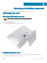
Page 13: ...rface to avoid scratches on the display 1 Follow the procedure in Before working inside your computer 2 Place the computer face down 3 Press and pull the USB dongle bay cover out of your computer Installing dongle bay cover 1 Align the tabs on the USB dongle bay cover into the slots on the back cover and snap the USB dongle bay cover into place 2 Follow the procedure in After working inside your c...

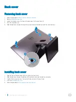
Page 14: ...top of the computer and lift the back cover off the inner frame 3 Installing back cover 1 Align the tabs on the back cover with the slots on the inner frame 2 Slide the back cover towards the bottom of the computer and snap the back cover in place 3 Tighten the two captive screws that secure the back cover to the inner frame 4 Install the USB dongle bay cover 5 Follow the procedure in After workin...

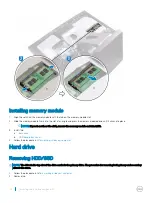
Page 15: ...B dongle bay cover b back cover 3 Using the tabs pry open the memory module shield 1 4 Using your fingertips spread apart the securing clips at each end of the memory module slot until the memory module pops out 2 5 Slide and remove the memory module from the memory module slot 3 Removing and installing components 15 ...

Page 16: ...the click remove the memory module and reinstall it 3 Install the a back cover b USB dongle bay cover 4 Follow the procedure in After working inside your computer Hard drive Removing HDD SSD NOTE The drive in the top slot of the drive carrier is the primary drive The procedure for removing both primary and secondary drive is the same 1 Follow the procedure in Before working inside your computer 2 ...

Page 17: ...ly push and lift the drive assembly out of the drive cage 2 5 Pry the drive bracket to release the tabs on the bracket from the slots on the HDD SSD 3 6 Slide the hard HDD SSD off the drive bracket 4 NOTE Note the orientation of the hard drive so that you can replace it correctly Removing and installing components 17 ...

Page 18: ...bly with the slots on the drive cage 4 Using the straps pull the drive assembly towards the back of the computer till it snaps into the drive interposer 5 Install the a back cover b USB dongle bay cover 6 Follow the procedure in After working inside your computer System board shield Removing system board shield 1 Follow the procedure in Before working inside your computer 2 Remove the a USB dongle...

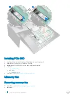
Page 19: ...he middle frame 3 Install the a back cover b USB dongle bay cover 4 Follow the procedure in After working inside your computer M 2 PCIe SSD Removing M 2 PCIe SSD 1 Follow the procedure in Before working inside your computer 2 Remove the a USB dongle bay cover b back cover c system board shield 3 Open the securing clip that secures the solid state drive to the system board 1 4 Slide and remove the ...

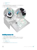
Page 20: ...ive slot 3 Secure the solid state drive to the system board using the securing clip 4 Install the a system board shield b back cover c USB dongle bay cover 5 Follow the procedure in After working inside your computer Memory fan Removing memory fan 1 Follow the procedure in Before working inside your computer 2 Remove the 20 Removing and installing components ...

Page 21: ...rom the system board 3 Installing memory fan 1 Connect the memory fan cable to the system board 2 Align the screw holes on the memory fan with the screw holes on the system board 3 Replace the four screws M2X3 that secure the memory fan to the system board 4 Install the a system board shield b back cover c USB dongle bay cover 5 Follow the procedure in After working inside your computer Removing a...

Page 22: ... eight captive screws that secure the processor heatsink to the system board 1 4 Remove the screw M3X4 that secures the processor heat sink fan to the middle frame 2 5 Lift the processor heatsink off the system board 3 NOTE Computers that support AMD Radeon Pro WX7100 and AMD Radeon Pro WX4150 graphics are shipped with seven captive screws Removing heatsink for computers with integrated graphics N...

Page 23: ...he processor heat sink to the system board 3 Replace the screw M3X4 that secures the processor heat sink fan to the middle frame 4 Install the a system board shield b back cover c USB dongle bay cover 5 Follow the procedure in After working inside your computer Processor Removing processor 1 Follow the procedure in Before working inside your computer 2 Remove the a USB dongle bay cover b back cove...

Page 24: ... the processor is not seated properly 2 Align the notches on the processor with the tabs on the processor socket and place the processor in the processor socket CAUTION Ensure that the processor cover notch is positioned underneath the alignment post 3 When the processor is fully seated in the socket close the processor cover 4 Pivot the release lever down and place it under the tab on the process...

Page 25: ...socket until the battery pops up and then lift the coin cell battery off its slot on the system board Installing coin cell battery 1 With the positive side facing up insert the coin cell battery into the battery socket and press down the battery into place 2 Install the a system board shield b back cover c USB dongle bay cover 3 Follow the procedure in After working inside your computer Removing a...

Page 26: ...rd shield to the system board 2 4 Lift the wireless card shield off the system board 3 5 Remove the screw M2X2 5 that secures the wireless card bracket and the wireless card to the system board 4 6 Lift the wireless card bracket off the wireless card 5 7 Disconnect the antenna cables from the wireless card 6 8 Slide and remove the wireless card out of the wireless card slot 7 26 Removing and insta...

Page 27: ... the screw hole on the wireless card bracket and wireless card with the screw hole on the system board 5 Replace the screw M2X2 5 that secures the wireless card bracket and the wireless card to the system board 6 Align the screw holes on the wireless card shield with the screw holes on the system board 7 Replace the two screws M2X2 5 that secure the wireless card shield to system board 8 Route the...

Page 28: ...w the procedure in After working inside your computer System fan Removing system fan 1 Follow the procedure in Before working inside your computer 2 Remove the a USB dongle bay cover b back cover c stand d system board shield 3 Remove the power supply unit cable from the routing guides on the system fan 1 4 Disconnect the power supply unit cable from its connector on the system board 2 28 Removing...

Page 29: ...stem fan cable from the system board 1 6 Remove the four screws M3X4 that secure the system fan to the middle frame 2 7 Lift the system fan along with its cable off the middle frame 3 Removing and installing components 29 ...

Page 30: ... the power supply unit cable to its connector on the system board 5 Route the power supply unit cable through the routing guides on the system fan 6 Install the a system board shield b stand c back cover d USB dongle bay cover 7 Follow the procedure in After working inside your computer Power supply unit Removing power supply unit 1 Follow the procedure in Before working inside your computer 2 Rem...

Page 31: ...ess the securing clip to release the power supply indicator cable from its connector 3 6 Press the securing clip to release the power supply fan cable from its connector 4 7 Open the securing clips and release the cables 5 8 Remove the five screws M3X4 that secure the power supply unit to the middle cover 6 9 Lift the power supply unit with the cable off the middle cover 7 Removing and installing ...

Page 32: ... close the clip to secure the cables 4 Connect the power supply indicator cable and power supply fan cable to their respective connectors 5 Route the power supply unit cable through the routing guides on system fan 6 Connect the power supply unit cable to its connector on the system board 7 Install the a back cover b USB dongle bay cover c stand 8 Follow the procedure in After working inside your ...

Page 33: ...king inside your computer 2 Remove the a USB dongle bay cover b back cover c stand 3 Remove 20 screws M3X4 that secure the inner frame to the middle frame 4 Gently pry the inner frame from the sides and lift it off the middle frame 2 Removing and installing components 33 ...

Page 34: ...cover c USB dongle bay cover 4 Follow the procedure in After working inside your computer Built in self test button Removing built in self test button 1 Follow the procedure in Before working inside your computer 2 Remove the a USB dongle bay cover b back cover c stand d inner frame 3 Remove the power button cable from the routing guide on the power button board shield 1 34 Removing and installing...

Page 35: ...on board on the middle frame 2 Align the screw holes on the Display Built in Self Test button board with the screw holes on the middle frame 3 Replace the two screws M2X3 that secure the Display Built in Self Test button board to the middle frame 4 Route the Display Built in Self Test button cable through the routing guides 5 Connect the Display Built in Self Test button cable to the power button ...

Page 36: ...b back cover c system board shield d stand e inner frame 3 Disconnect the microphone cable from the system board 1 4 Remove the four screws M2X2 2 that secure the microphone module to the middle frame 2 5 Release microphone cable from the routing guides on the middle frame 3 6 Using a plastic scribe carefully pry and lift the microphone modules 4 with the cable off the slots on the middle frame 4 ...

Page 37: ... middle frame 3 Replace the four screws M2X2 2 that secure the microphone module to the middle frame 4 Connect the microphone cable to the system board 5 Install the a inner frame b stand c system board shield d back cover e USB dongle bay cover 6 Follow the procedure in After working inside your computer Removing and installing components 37 ...

Page 38: ...ecuring clip to release the power button cable from its connector 1 4 Press the securing clip to release the diagnostic button and light cable from its connector 2 5 Disconnect the USB dongle cable from the system board 3 6 Remove the four screws M3X4 that secure the I O panel to the middle frame and system board 1 7 Lift the I O panel off the middle frame 2 38 Removing and installing components ...

Page 39: ...s on the I O board panel with the screw holes on the middle frame 5 Replace the four screws M3X4 that secure the I O panel to the middle frame and system board 6 Connect the diagnostic button and light cable 7 Connect the power button cable 8 Install the a inner frame b stand c system board shield d back cover e USB dongle bay cover 9 Follow the procedure in After working inside your computer Remo...

Page 40: ...ongle bay cover b back cover c stand d inner frame e system board shield f I O panel 3 Remove the three screws M3X4 that secure the USB dongle port to the I O panel 4 Remove the USB dongle port cable from the routing guide on I O panel 2 5 Remove the USB dongle port from the I O panel 3 40 Removing and installing components ...

Page 41: ...ign the screw holes on the USB dongle port with the screw holes on the I O panel 4 Replace the three screws M3X4 that secure the USB dongle port to the I O panel 5 Install the a I O panel b system board shield c inner frame d stand e back cover f USB dongle bay cover 6 Follow the procedure in After working inside your computer Removing and installing components 41 ...

Page 42: ...efore working inside your computer 2 Remove the a USB dongle bay cover b back cover c stand d system board shield e inner frame f I O panel 3 Spread apart the securing tabs to release the I O panel bracket from the I O panel 4 Lift the I O panel bracket off the I O panel 42 Removing and installing components ...

Page 43: ...the screw that secures the power diagnostic button and light board to the I O panel bracket 1 6 Lift the power diagnostic button and light board off the I O panel bracket 2 Removing and installing components 43 ...

Page 44: ...er frame c system board shield d stand e back cover f USB dongle bay cover 5 Follow the procedure in After working inside your computer Drive cage Removing HDD SSD cage 1 Follow the procedure in Before working inside your computer 2 Remove the a USB dongle bay cover b back cover c stand d hard drive e system board shield f I O panel 3 Remove the cable from the routing guide on drive cage 1 4 Open ...

Page 45: ...7 Remove the four screws M3X4 that connect the drive cage to the middle frame 1 8 Lift the hard drive cage off the middle frame 2 Removing and installing components 45 ...

Page 46: ...9 Remove the four screws M2X3 that connect the interposer to the hard drive cage 1 10 Remove the interposer from the hard drive cage 2 46 Removing and installing components ...

Page 47: ...he drive cage 6 Route the cables through the guide and close the clip to secure the cables 7 Install the a I O panel b system board shield c stand d hard drive e back cover f USB dongle bay cover 8 Follow the procedure in After working inside your computer Converter board Removing converter board 1 Follow the procedure in Before working inside your computer 2 Remove the a USB dongle bay cover b ba...

Page 48: ...6 Remove the three screws M3X4 that secure the converter board to the middle frame 1 7 Lift the converter board off the middle frame 2 48 Removing and installing components ...

Page 49: ...he converter board to the middle frame 3 Connect the converter board cable to the converter board 4 Connect the backlight power cables to the converter board 5 Install the a I O panel b inner frame c system board shield d stand e back cover f USB dongle bay cover 6 Follow the procedure in After working inside your computer Removing and installing components 49 ...

Page 50: ...USB dongle bay cover b back cover c system board shield d stand e inner frame 3 Disconnect the speaker cable from the system board and release it from the routing guides on middle frame 1 2 4 Remove the eight screws M3x4 that secure the speakers to the middle frame 1 50 Removing and installing components ...

Page 51: ...es on the middle frame 2 Replace the eight screws M3x4 that secure the speakers to the middle frame 3 Route the cable through the routing guides on middle frame and connect the speaker cable to the system board 4 Install the a inner frame b stand c system board shield d back cover e USB dongle bay cover Removing and installing components 51 ...

Page 52: ...Remove the power button cable from the routing guide on the power button board shield 1 4 Remove the two screws M2X3 that secure the power button board shield to the middle frame 2 5 Slide and remove the power button board shield off the middle frame 3 6 Lift the power button board off the slot on the middle frame 4 7 Disconnect the power button board cable from the power button board 5 8 Disconne...

Page 53: ...the power button cable through the routing guides on the power button board shield Media card reader Removing media card reader 1 Follow the procedure in Before working inside your computer 2 Remove the a USB dongle bay cover b back cover c stand d inner frame e speakers 3 Remove two screws M2X3 that secure the media card reader shield to the middle frame 1 4 Lift the media card reader shield off ...

Page 54: ... c stand d back cover e USB dongle bay cover 7 Follow the procedure in After working inside your computer Camera Removing camera 1 Follow the procedure in Before working inside your computer 2 Remove the a USB dongle bay cover b back cover c stand d inner frame e speakers 3 Remove the two screws M2X3 that secure the camera assembly to the middle frame 1 4 Remove the camera cable from the routing g...

Page 55: ...ddle frame 3 Align the screw holes on the camera assembly with the screw holes on the middle frame 4 Replace the two screws M2X3 that secure camera assembly to the middle frame 5 Install the a speakers b inner frame c stand d back cover e USB dongle bay cover 6 Follow the procedure in After working inside your computer Removing and installing components 55 ...

Page 56: ... board shield h I O panel i processor heat sink j processor k coin cell battery l memory fan m wireless card n solid state drive 3 Using the pull tab disconnect the display cable from the system board 3 4 Disconnect the camera cable from the system board 2 5 Using the pull tab disconnect the USB connection cable from the system board 3 6 Disconnect the hard drive power cable from the system board ...

Page 57: ...he pull tab disconnect the media card reader cable from the system board 3 11 Disconnect the audio cable from the system board 4 12 Remove the screw M3X4 that secures the media card reader cable and audio cable to the system board 5 13 Disconnect the microphone cable from the system board 6 Removing and installing components 57 ...

Page 58: ...14 Remove the 12 screws M3X4 that secure the system board to the middle frame 1 15 Lift the system board off the middle frame 2 58 Removing and installing components ...

Page 59: ... Connect the microphone cable audio cable media card reader cable and converter board cable to their respective connectors on the system board 5 Connect the media card reader cable webcam cable and display cable to their respective connectors on the system board 6 Install the a solid state drive b wireless card c memory fan d coin cell battery e processor f processor heat sink g I O panel h system...

Page 60: ... 5 memory module slot 6 system fan connector 7 wireless card slot 8 audio cable connector 9 media card connector 10 SSD card connector M 2 11 speaker cable connector 12 converter board cable connector 13 memory fan cable connector 14 USB 3 0 ports 4 15 HDMI port 16 Line out port 17 displayport 18 network port 19 Thunderbolt 3 USB Type C port 20 Thunderbolt 3 USB Type C port 21 power supply unit ca...

Page 61: ...e g system board shield h I O panel i processor heat sink j processor k coin cell battery l memory fan m wireless card n solid state drive o system board 3 Press the tabs on the cable to release it from the connector 1 4 Disconnect the cable from its slot on the middle frame 2 5 Press the tabs on the backlight cable 3 6 Disconnect the backlight cable from its slot on the middle frame 4 7 Open the ...

Page 62: ...he backlight cable to its slot on the middle frame 3 Connect the converter board cable to its slot on the middle frame 4 Install the a system board b solid state drive c wireless card d memory fan e coin cell battery f processor g processor heat sink h I O panel i system board shield j inner frame k system fan l stand 62 Removing and installing components ...

Page 63: ...3 system board shield 4 stand 5 inner frame 6 I O panel 7 speakers 8 camera NOTE The middle frame can also be removed by removing all the components given in the steps below In this scenario the user has to remove 13 screws that secure the middle frame to the display panel and speaker bezel 1 Follow the procedure in Before working inside your computer 2 Remove the a USB dongle bay cover b back cov...

Page 64: ...he middle frame 3 6 Lift the display cable off the middle frame 4 7 Press the tabs on the backlight cable 5 8 Disconnect the backlight cable from its slot on the middle frame 6 9 Remove the seven screws M3X4 that secure the middle frame to the display panel 1 10 Remove the six screws M2X3 that secure the middle frame to the speaker bezel 2 11 Lift the middle frame off the display 3 64 Removing and...

Page 65: ...ith the screw holes on the speaker bezel 4 Replace the six screws M2X3 that secure the middle frame to the speaker bezel 5 Open the latch and connect the display cable to its slot on the middle frame 6 Connect the backlight cable to its slot on the middle frame 7 Connect the converter board cable to its slot on the middle frame 8 Install the a display built in self test button board b system board...

Page 66: ...el a camera b speakers c I O panel d inner frame e system board shield f stand g back cover h USB dongle bay cover 9 Follow the procedure in After working inside your computer Speaker bezel Removing speaker bezel NOTE The following steps are applicable only for non touch systems 1 Follow the procedure in Before working inside your computer 2 Remove the a USB dongle bay cover b back cover c system ...

Page 67: ... I O panel e inner frame f stand g system board shield h back cover i USB dongle bay cover 2 Follow the procedure in After working inside your computer Display panel Removing display panel NOTE The following steps are applicable only for non touch systems 1 Follow the procedure in Before working inside your computer 2 Remove the a USB dongle bay cover Removing and installing components 67 ...

Page 68: ...el g speakers h camera i middle frame j speaker bezel We are left with the display panel Installing display panel NOTE The following steps are applicable only for non touch systems 1 Place the display panel over the speaker bezel 68 Removing and installing components ...

Page 69: ...2 Place the middle frame on the assembly Removing and installing components 69 ...

Page 70: ...e the middle frame to the speaker bezel 3 4 Replace the seven screws M3X4 that secure the middle frame to the display panel 4 5 Turn the display assembly over 5 6 Peel off the Mylar from the display panel 70 Removing and installing components ...

Page 71: ...nel Peeling off the Mylar can result in one of the two following acceptable scenarios a A portion of Mylar remains in the middle frame b The whole Mylar is peeled off from the display assembly 7 Install the a speaker bezel b middle frame Removing and installing components 71 ...

Page 72: ...mera d speakers e I O panel f inner frame g stand h system board shield i back cover j USB dongle bay cover 8 Follow the procedure in After working inside your computer 72 Removing and installing components ...

Page 73: ...Quad Core 3 4GHz 3 8Ghz Turbo 6MB 7th generation supports Windows 10 Linux Intel Xeon Processor E3 1275 v5 Quad Core HT 3 6Ghz 4 0GHz Turbo 8MB supports Windows 7 10 Intel Core i7 6700 Quad Core 3 40GHz 4 0Ghz Turbo 8MB 6th generation supports Windows 7 10 Intel Xeon Processor E3 1245 v5 Quad Core HT 3 5GHz 3 9Ghz Turbo 8MB supports Windows 7 10 Intel Core i5 6600 Quad Core 3 3GHz 3 9Ghz Turbo 6MB...

Page 74: ... Technology Intel Integrated Graphics Intel HD graphics exceptional videos editing smallest details in the videos Intel Quick Sync Video excellent video conferencing capability quick video editing and authoring Intel Clear Video HD visual quality and color fidelity enhancements for HD playback and immersing web browsing Integrated memory controller Intel Smart Cache Optional Intel vPro technology ...

Page 75: ...lick the desktop 2 Select Start Task Manager The Windows Task Manager window is displayed 3 Click the Performance tab in the Windows Task Manager window The processor performance details are displayed 4 Click Open Resource Monitor Chipsets All Desktops communicate with the CPU through the chipset This system is shipped with the Intel C236 series chipset Downloading the chipset driver 1 Turn on the...

Page 76: ... and search for the chipset Display options Identifying the display adapters in Windows 7 1 Start the Search Charm and select Settings 2 Type Device Manager in the search box and tap Device Manager from the left pane 3 Expand Display adapters Identifying the display adapters in Windows 10 1 Click All Settings on the Windows 10 Action bar 2 Click Control Panel select Device Manager and expand Displ...

Page 77: ...s computer supports up to two SSD HDD and one M 2 PCIe SSD Hard drive options This computer supports up to two HDD SSD Identifying the hard drive in Windows 7 1 Click Start Control Panel Device Manager The hard drive is listed under Disk drives 2 Expand Disk drives Identifying the hard drive in Windows 10 1 Click All Settings on the Windows 10 Charms Bar 2 Click Control Panel select Device Manager...

Page 78: ...r transfer rates up to 5 Gbps Increased maximum bus power and increased device current draw to better accommodate power hungry devices New power management features Full duplex data transfers and support for new transfer types Backward USB 2 0 compatibility New connectors and cable The topics below cover some of the most commonly asked questions regarding USB 3 0 Speed Currently there are 3 speed ...

Page 79: ...ideo solutions should work that much better Single link DVI requires almost 2Gbps throughput Where 480Mbps was limiting 5Gbps is more than promising With its promised 4 8Gbps speed the standard will find its way into some products that previously weren t USB territory like external RAID storage systems Listed below are some of the available SuperSpeed USB 3 0 products External Desktop USB 3 0 Hard...

Page 80: ...the page and expand Chipset 6 Click Download to download the USB 3 0 driver 7 After the download is complete navigate to the folder where you saved the USB 3 0 driver file 8 Double click the USB 3 0 driver file icon and follow the instructions on the screen HDMI This computer supports HDMI to connect a TV or another HDMI in enabled device It provides video and audio output The HDMI port is located...

Page 81: ...rvice Tag of your computer and click Submit NOTE If you do not have the Service Tag use the auto detect feature or manually browse for your computer model 4 Click Drivers downloads Find it myself 5 Scroll down the page and expand Network 6 Click Download to download the Wi Fi driver for your computer 7 After the download is complete navigate to the folder where you saved the Wi Fi driver file 8 Do...

Page 82: ...ick the Windows button and select All Settings System 2 Under System click About Windows 7 1 Click Start Control Panel System Verifying system memory in setup 1 Turn on or restart your computer 2 Perform one of the following actions after the Dell logo is displayed With keyboard Tap F2 until the Entering BIOS setup message appears Without keyboard To enter the Boot section menu tap F12 3 On the le...

Page 83: ... refresh its memory Deep power down mode is expected to reduce standby power consumption by 40 to 50 percent DDR4 Details There are subtle differences between DDR3 and DDR4 memory modules as listed below Key notch difference The key notch on a DDR4 module is in a different location from the key notch on a DDR3 module Both notches are on the insertion edge but the notch location on the DDR4 is slig...

Page 84: ...on your computer 2 Go to Dell com support 3 Click Product Support enter the Service Tag of your computer and click Submit NOTE If you do not have the Service Tag use the auto detect feature or manually browse for your computer model 4 Click Drivers downloads 5 Click Find it myself 6 Scroll down the page and expand Chipset 7 Click Download to download the media card reader driver for your computer ...

Page 85: ...and Audio 6 Click Download to download the audio driver 7 Save the file and after the download is complete navigate to the folder where you saved the audio driver file 8 Double click the audio driver file icon and follow the instructions on the screen to install the driver Operating System This computer is shipped with the Windows 10 factory installation Service tag location The service tag is a u...

Page 86: ...86 Technology and components ...

Page 87: ...gnostics and BIOS Setup options are also included in this menu The devices listed on the boot menu depend on the bootable devices in the system This menu is useful when you are attempting to boot to a particular device or to bring up the diagnostics for the system Using the boot menu does not make any changes to the boot order stored in the BIOS The options are Legacy Boot Internal HDD Onboard NIC...

Page 88: ...ss Service Code and click Submit ClickDetect Product and follow the instructions on screen 3 If you are unable to detect or find the Service Tag click the Choose from all products 4 Choose the Products category from the list NOTE Choose the appropriate category to reach the product page 5 Select your computer model and the Product Support page of your computer appears 6 Click Get drivers and click...

Page 89: ...nced Boot Options Allows you to select the Enable Legacy Option ROMs option when in UEFI boot mode Allows you to select the Enable Attempt Legacy Boot option Date Time Allows you to set the date and time settings Changes to the system date and time take effect immediately Table 8 System Configuration Option Description Integrated NIC Allows you to control the on board LAN controller The option Ena...

Page 90: ...ult Touchscreen This field controls whether the touchscreen is enabled or disabled Miscellaneous Allows you to enable or disable the various on board devices Enable camera default Secure Digital SD Card default Disable Media Card Table 9 Video Option Description Switchable Graphics This option sets the operating mode of the system s graphics hardware Disabled Enabled Table 10 Security Option Descr...

Page 91: ...ating system TPM On default Clear disabled PPI Bypass for Enable Commands PPI Bypass for Disable Commands Disabled Enabled default Computrace This field lets you Activate or Disable the BIOS module interface of the optional Computrace Service from Absolute Software Enables or disables the optional Computrace service designed for asset management Deactivate This option is selected by default Disabl...

Page 92: ...s the selected key Reset All Keys Resets to default setting Delete All Keys Deletes all the keys NOTE If you disable the Custom Mode all the changes made will be erased and the keys will restore to default settings Table 12 Intel Software Guard Extensions Option Description Intel SGX Enable Allows you to enable or disable the Intel Software Guard Extensions to provide a secured environment for run...

Page 93: ... Control Allows you to define the controls when Deep Sleep is enabled Disabled Enabled in S5 only Enabled in S4 and S5 This option is Enabled in S4 and S5 by default Fan Control Override Allows you to determine the speed of the system fan When this option is enabled the system fan runs at the maximum speed This option is disabled by default USB Wake Support Allows you to enable the USB devices to ...

Page 94: ... a Virtual Machine Monitor VMM can utilize the additional hardware capabilities provided by Intel Virtualization Technology Enable Intel Virtualization Technology This option is selected by default VT for Direct I O Enables or disables the Virtual Machine Monitor VMM from utilizing the additional hardware capabilities provided by Intel Virtualization technology for direct I O Enable VT for Direct ...

Page 95: ...ou to recover the corrupted BIOS conditions from the recovery files on the primary hard drive The option BIOS Recovery from Hard Drive is selected by default Table 19 System Logs Option Description BIOS Events Displays the system event log and allows you to Clear Log Mark all Entries Table 20 SupportAsssist System Resolution Option Description Auto OS Recovery Threshold Options off 1 2 default 3 S...

Page 96: ...mputer and then click Submit NOTE If you do not have the Service Tag use the auto detect feature or manually browse for your computer model 4 Click Drivers and Downloads 5 Click Find it myself tab 6 Select the operating system installed on your computer 7 Scroll down the page and select the graphic driver to install 8 Click Download File to download the graphic driver for your computer 9 After the...

Page 97: ...Software 97 ...

Page 98: ...rom dell com support In the Device Manager check if the Bluetooth driver is installed Install the driver updates from dell com support Intel Trusted Execution Engine Interface In the Device Manager check if the Intel Trusted Execution Engine Interface driver is installed Install the driver updates from Dell com support 98 Software ...

Page 99: ...Intel Serial IO Driver In the Device Manager check if the Intel Serial IO Driver is installed Install the driver updates from dell com support Software 99 ...

Page 100: ...100 Software ...

Page 101: ...Intel chipset drivers Verify if the Intel chipset drivers are already installed in the computer Graphics drivers Verify if the graphics drivers are already installed in the computer Software 101 ...

Page 102: ...the silicon manufacturing process that enhances the trust security effectiveness Every TPM must have an owner before it can be utilized The TPM user must be physically present to take ownership After this procedure is completed and the TPM has a unique owner the TPM is activated TPM 2 0 Installing Dell TPM Update utility for Windows DOS 1 Download the TPM file from Dell com support 2 Click Downloa...

Page 103: ...ment Browse to the location where you downloaded the file and double click the new file Windows System will auto restart and update the TPM during the system startup When the TPM update is complete the system will auto reboot to take effect When the TPM update is complete the system will auto reboot to take effect Run the TPM update utility from DOS environment if Legacy Boot mode Non Windows user...

Page 104: ...times followed by a pause This 2 3 pattern continues until the computer is turned off indicating the Recovery image is not found The following table shows different light patterns and what they indicate Table 22 System diagnostic lights Light pattern Problem description 2 1 System board error 2 2 System board or power supply unit or power supply cable error 2 3 System board or memory or CPU error ...

Page 105: ...the LCD during troubleshooting to determine which sub system is at fault The main difference is the lack of an integrated keyboard scan controller in the AIO When BIST is initiated an internal generated pattern from the LCD is emitted for user s observation This pattern goes by sequence through this pattern Black White Red Green Blue or a White Black Red Green Blue where each pattern is emitted fo...

Page 106: ...106 Troubleshooting ...

Page 107: ...Initiating BIST 1 Shut down the system 2 Hold down the BIST button and press the power button Troubleshooting 107 ...

Page 108: ...onnectors Display specifications Storage specifications Port and connector specifications Power specifications Camera specifications Stand specifications Physical specifications Environmental specifications System specifications Feature Specification Processor type Intel Xeon Processor E3 1200 v6 Family 7th generation Intel Core i7 i5 Intel Xeon Processor E3 1200 v5 Family 6th generation Intel Cor...

Page 109: ...able 23 Video specifications Integrated Discrete Controller Intel HD Graphics 530 AMD Radeon Pro WX 7100 with 8 GB GDDR5 dedicated memory AMD Radeon Pro WX 4150 with 4 GB GDDR5 dedicated memory Operating Systems Graphics Video API Support OpenGL 4 4 DirectX 11 1 Win8 1 DirectX 12 Win10 External display support HDMI 1 4 DisplayPort 1 2 Audio specifications Feature Specification Controller Integrate...

Page 110: ...2 card One M 2 slot for SSD One M 2 slot for Wi Fi and Bluetooth combo card Display specifications Feature Specification Type UltraSharp 4K Ultra HD Touch and Non Touch Diagonal length 27 inches Native Resolution HD 3840x2160 Refresh rate 60 Hz Operating angle 85 degrees horizontal 85 degrees vertical Pixel pitch HD 0 144 mm Storage specifications Feature Specification Storage Up to two 2 5 inch H...

Page 111: ...0A Frequency 50 Hz to 60 Hz Camera specifications Video conference online with an optional built in camera Windows Hello feature can be enabled with IR Camera embeded Feature Specification Image resolution 1 0 megapixels Video resolution HD 720p Diagonal viewing angle 74 6 degrees Stand specifications Table 24 Articulating stand for touch SKU only Feature Specification Tilt Forward 5 Back 60 Width...

Page 112: ... in Environmental specifications Temperature Specifications Operating 0 C to 35 C 32 F to 95 F Storage 40 C to 65 C 40 F to 149 F Relative humidity maximum Specifications Operating 10 to 90 non condensing Storage 0 to 95 non condensing Maximum vibration Specifications Operating 0 66 GRMS Storage 1 30 GRMS Shock maximum Specifications Operating 110 G Storage 160 G Altitude maximum Specifications Op...

Page 113: ... service options Availability varies by country and product and some services may not be available in your area To contact Dell for sales technical support or customer service issues 1 Go to Dell com support 2 Select your support category 3 Verify your country or region in the Choose a Country Region drop down list at the bottom of the page 4 Select the appropriate service or support link based on...

Reviews: