


10.
To complete the removal procedure, see
Configuring Your Computer After Removing or Installing a PCI or PCI Express Card
.
Replacing PCI and PCI Express Cards
1.
Follow the procedures in
Before You Begin
.
2.
Remove the computer cover (see
Removing the Computer Cover
).
3.
Remove the card retention bracket (see
Removing the Card Retention Bracket
).
4.
If this is a new card installation, remove the filler bracket covering the card-slot opening.
5.
Prepare the card for installation.
See the documentation that came with the card for information on configuring the card, making internal connections, or otherwise customizing it for your
computer.
6.
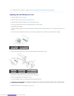
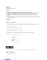
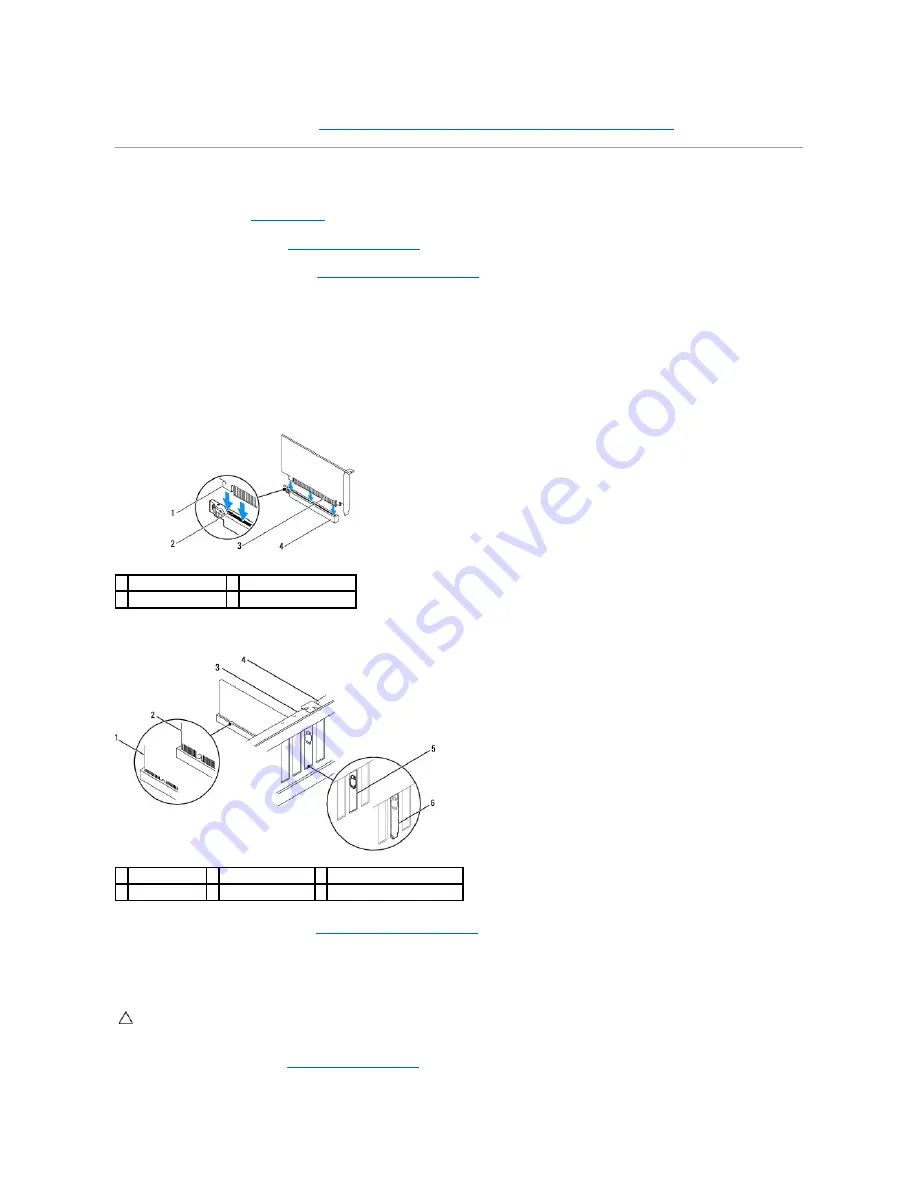
If you are installing the PCI Express card into the x16 card connector, position the card so the securing slot is aligned with the securing tab.
7.
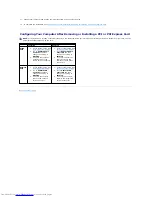
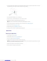
Place the card in the connector and press down firmly. Ensure that the card is fully seated in the slot.
8.
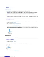
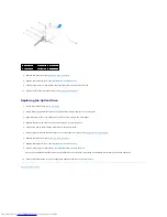
Replace the card retention bracket (see
Replacing the Card Retention Bracket
).
9.
Connect any cables that should be connected to the card.
See the documentation for the card for information about the card's cable connections.
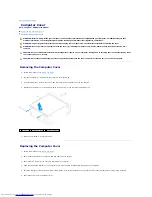
10.
Replace the computer cover (see
Replacing the Computer Cover
).
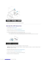
1 securing tab
2 securing slot
3 PCI Express x16 card 4 PCI Express x16 card slot
1 fully-seated card 2 not fully-seated card 3 alignment bar
4 alignment guide 5 bracket within slot
6 bracket caught outside of slot
CAUTION:
Do not route card cables over or behind the cards. Cables routed over the cards can prevent the computer cover from closing properly
or cause damage to the equipment.
Summary of Contents for Inspiron 580
Page 5: ...Back to Contents Page ...


