


Back to Contents Page
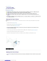
Power Supply
Dell™ Inspiron™ 620 Service Manual
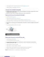
Removing the Power Supply
Replacing the Power Supply
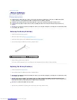
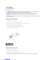
Removing the Power Supply
1.
Follow the instructions in
Before You Begin
.
2.
Remove the computer cover (see
Removing the Computer Cover
).
3.
Disconnect the DC power cables from the system board and the drives (see
System Board Components
).
4.
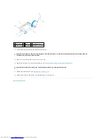
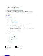
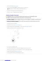
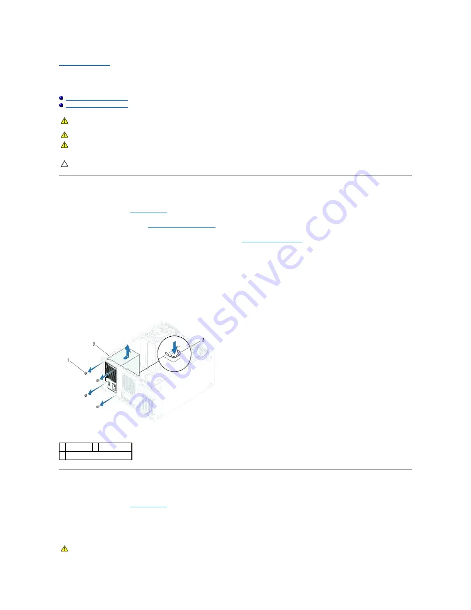
Remove the four screws that secure the power supply to the chassis.
5.
Press the power supply clamp to release the power supply from the chassis.
6.
Slide and lift the power supply away from the chassis.
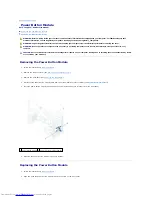
Replacing the Power Supply
1.
Follow the instructions in
Before You Begin
.
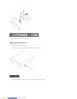
2.
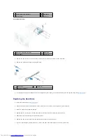
Slide the power supply towards the back of the chassis.
3.
Align the screw holes on the power supply with the screw holes on the chassis.
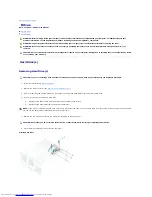
WARNING:
Before working inside your computer, read the safety information that shipped with your computer. For additional safety best
practices information, see the Regulatory Compliance Homepage at dell.com/regulatory_compliance.
WARNING:
To guard against electrical shock, always unplug your computer from the electrical outlet before removing the cover.
WARNING:
Do not operate your computer with any cover(s) (including computer covers, bezels, filler brackets, front-panel inserts, etc.)
removed.
CAUTION:
Only a certified service technician should perform repairs on your computer. Damage due to servicing that is not authorized by Dell is
not covered by your warranty.
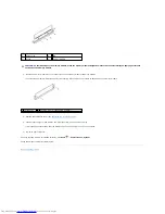
1 screws (4) 2 power supply
3 power supply clamp
WARNING:
Failure to replace and tighten all screws may cause electrical shock as these screws are a key part of the system grounding.


