background image

Keyboard and Mouse Connectors Overview 

Your system uses a Personal System/2 (PS/2)-style keyboard and supports a PS/2-compatible mouse. Cables from both devices attach to 6-pin 
miniature 

Deutsche Industrie Norm

 (DIN) connectors on the back panel of your computer. Either device can connect to either connector. 

A PS/2-compatible mouse works identically to an industry-standard serial mouse or bus mouse except that it has its own dedicated connector, 
which frees up both serial ports and does not require an expansion card. Circuitry inside the mouse detects the movement of a small ball and 
relays the direction to the computer. 

Mouse driver software can give the mouse priority with the microprocessor by issuing IRQ12 whenever a new mouse movement is made. The 
driver software also passes along the mouse data to the application program that is in control. 

Keyboard Connector 

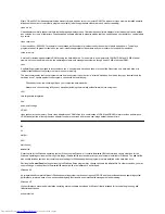
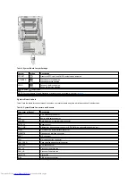
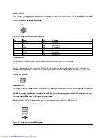
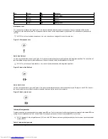
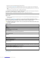
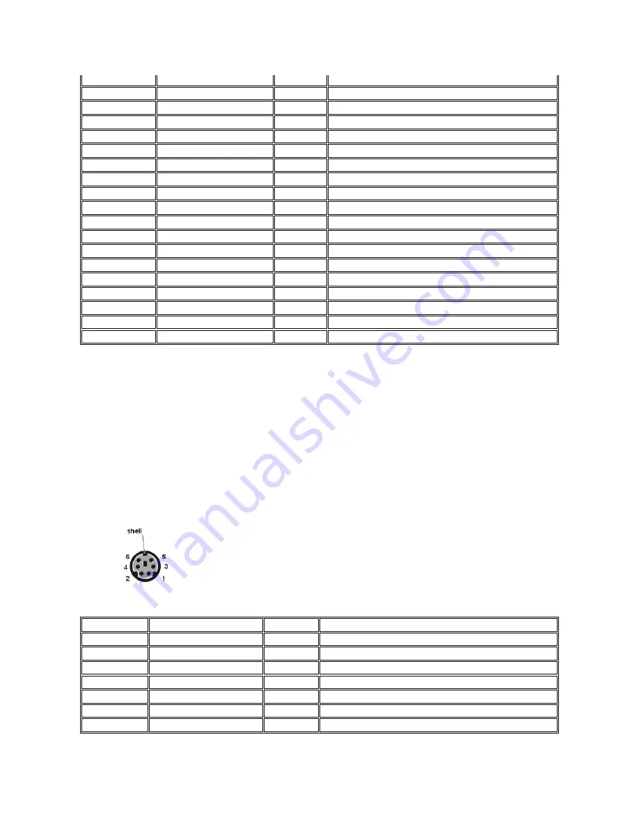
If you reconfigure your hardware, you may need pin number and signal information for the keyboard connector. Figure 7 illustrates the pin numbers 
for the keyboard connector, and Table 6 lists and defines the pin assignments and interface signals for the keyboard connector. 

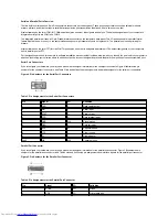
Figure 7. Pin Numbers for the Keyboard Connector


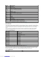
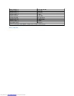
Table 6. Pin Assignments for the Keyboard Connector


48

DPARL

I/O

SCSI data parity low

49-50

GND

N/A

Signal ground

51-52

TRMPWR

N/A

Terminator power

53

RSVD

N/A

Reserved

54

GND

N/A

Signal ground

55

ATN

I/O

SCSI attention

56

GND

N/A

Signal ground

57

BSY

I/O

SCSI busy

58

ACK

I/O

SCSI acknowledge

59

RST

I/O

SCSI reset

60

MSG

I/O

SCSI message

61

SEL

I/O

SCSI select

62

C/D

I/O

SCSI command/data

63

REQ

I/O

SCSI request

64

I/O

I/O

SCSI in/out

65

D8

I/O

SCSI data bit 8

66

D9

I/O

SCSI data bit 9

67

D10

I/O

SCSI data bit 10

68

D11

I/O

SCSI data bit 11


Pin

Signal

I/O

Definition

1

KBDATA

I/O

Keyboard data

2

NC

N/A

No connection

3

GND

N/A

Signal ground

4

FVcc

N/A

Fused supply voltage

5

KBCLK

I/O

Keyboard clock

6

NC

N/A

No connection

Shell

N/A

N/A

Chassis ground

Summary of Contents for Inspiron 620

Page 1: ...vell and NetWare are registered trademarks of Novell Inc UNIX is a registered trademark of The Open Group in the United States and other countries VESA is a registered trademark of Video Electronics Standards Association As an ENERGY STAR Partner Dell Computer Corporation has determined that this product meets the ENERGY STAR guidelines for energy efficiency Other trademarks and trade names may be...

Page 2: ...uter system supports most standard speakers that have integrated amplifiers You can purchase speakers separately from Dell Connect the audio cable from the speakers to the audio line out jack see Figure 1 Microphones Overview Using Audio Utilities Connecting Audio Devices Installing Audio Drivers Adjusting Volume NOTE The instructions in this section apply to systems using the integrated audio con...

Page 3: ... green Telephony Application Programming Interface TAPI pocket connector on the system board Adjusting Volume Use the instructions in the following subsections to adjust the speaker balance and volume of an audio source that uses the integrated audio controller in your Dell computer or to mute the internal speaker Adjusting Volume in the Microsoft Windows NT 4 0 Operating System 1 Double click the...

Page 4: ...t your selected audio input device l Use the Master Out volume control to adjust sound levels from several different audio sources For detailed instructions for using either device see your Windows NT documentation Installing Audio Drivers Dell installed your system s audio drivers and they are operative when you receive the system no further installation or configuration is needed For information...

Page 5: ...eep code see Messages and Codes l Verify the settings in System Setup l Run the Dell Diagnostics Checking Connections and Switches Improperly set switches and controls and loose or improperly connected cables are the most likely source of problems for your computer monitor or other peripheral such as a printer keyboard mouse or other external equipment To check all connections and switches perform...

Page 6: ...r of RIMMs replace an existing pair of RIMMs with the spare pair and then reboot Repeat this procedure with each pair of RIMMs until you identify the faulty or improperly seated RIMM l A solid green power indicator no beep code and no video during POST indicate that the monitor or the integrated video controller may be faulty See Troubleshooting the Monitor If the monitor is operating properly and...

Page 7: ...figuration does not match the information recorded by System Setup an error message may appear on your screen This problem can happen if you changed your system s hardware configuration and forgot to run System Setup To correct this problem enter System Setup correct the setting for the corresponding System Setup program option and reboot your system If after checking the settings in System Setup ...

Page 8: ...Expansion Cards SuprFreq Utility Program Adding Memory Replacing the System Battery Removing and Installing a Memory Expansion Card 1 Processor fan connector 22 MT power 2 connector 2 Diskette drive connector 23 Auxiliary audio input connector 3 Slot 2 processor 0 socket 24 Auxiliary drive access connector 4 Slot 2 processor 1 socket 25 MT power 1 connector 5 CD ROM drive audio connector 26 Card c...

Page 9: ... configuring the card making internal connections and customizing it for your system 12 Processor mismatch LED 33 32 bit PCI expansion card connectors 3 13 Memory expansion card B connector 34 AGP Pro graphics card connector 14 System board thumbscrew 35 Network connector 15 Suspend to RAM LED 36 Diagnostic LEDs 16 Memory expansion card A connector 37 USB connectors 17 LVD SCSI connector 38 Microp...

Page 10: ...irmly seated in the connector secure the card s mounting bracket to the chassis with the screw that you removed in step 3 6 Connect any cables that should be attached to the card See the documentation that came with the card for information about the card s cable connections 7 Replace the AGP card brace 8 Replace the computer cover reconnect the network cable and phone line if present reconnect yo...

Page 11: ...odule of each pair in the corresponding numbered socket on each MEC Figure 5 RIMM Socket Sequence NOTE If a setup password has been assigned by someone else contact the network administrator for information on resetting the chassis intrusion detector NOTICE See Protecting Against Electrostatic Discharge in your Dell Precision WorkStations System Information Guide NOTE Installing filler brackets ov...

Page 12: ... until the securing tabs snap into place around the ends of the memory module Figure 7 Installing a RIMM To remove a memory module press the securing clips outward simultaneously until the module disengages from the socket see Figure 8 It should pop out slightly Figure 9 Removing a RIMM 1 RIMM1_A 2 RIMM2_A 3 RIMM3_B 4 RIMM4_B NOTICE See Protecting Against Electrostatic Discharge in your Dell Preci...

Page 13: ... total is correct press the Esc key to exit the System Setup program 11 Run the Dell Diagnostics to verify that the memory modules are operating properly Removing and Installing a Memory Expansion Card To remove a MEC perform the following steps 1 Remove the computer cover 2 Rotate the green MEC cover up until it frees the MEC from its socket see Figure 11 Pull the MEC from the system Figure 11 Re...

Page 14: ...lete the one time registration process if you have not already done so 3 Click Dell Knowledge Base under Support Tools enter second processor in the Search Documents by Words in Title option and click Go 4 Click the document title that corresponds to the operating system you are running Each processor and its associated level 2 L2 cache memory are contained in a single edge contact SEC cartridge t...

Page 15: ...minator card from the second SEC cartridge connector labeled PROC_0 or PROC_1 by pulling the terminator card straight out to release it from the connector 5 If you are replacing an installed processor remove the processor by performing the following steps a Unplug the processor fan wire from the system board see Figure 1 b Grasp the installed SEC cartridge heat sink assembly firmly and pull it awa...

Page 16: ...NT 4 0 the operating system detects the second processor 13 Run the Dell Diagnostics to verify that the new processor is operating correctly See Troubleshooting for information on running the diagnostics and troubleshooting any problems that may occur SuprFreq Utility Program SuprFreq is an MS DOS utility program used to correctly set the processor s core frequency based on a multiplier ratio of t...

Page 17: ... and a 2 8 volt processor cartridge respectively see Figure 14 Figure 14 Processor Cartridge Label Compare System Processor s Speed with Processor s Maximum Core Speed Run the SuprFreq utility program if the system processor s speed does not match the processor s maximum core speed Downloading the SuprFreq Utility Program 1 Go to http support dell com If you have not created a profile for your spe...

Page 18: ...er shunt bypass on the RTCRST jumper see Figure 2 Make a copy of your system configuration information in the System Setup Refer to your written or printed copy of the system configuration information to restore the correct settings after resetting the processor speed 4 Remove the coin cell system battery Pry the battery out of its socket with your fingers or with a blunt nonconductive object such...

Page 19: ...guration options To replace the system battery with another CR2032 coin cell battery perform the following steps 1 Make a copy of your system configuration information in the System Setup If the settings are lost while you are replacing the battery refer to your written or printed copy of the system configuration information to restore the correct settings 2 Remove the computer cover 3 To access t...

Page 20: ...o restore the correct settings for the system configuration information using the copy made in step 1 9 While in System Setup reset the chassis intrusion detector by selecting System Security and changing Chassis Intrusion to Enabled Enabled Silent or Disabled 10 Turn off your computer and unplug it for at least 10 minutes 11 After 10 minutes plug in and turn on the computer and enter the System S...

Page 21: ...es and city codes For example to call Paris France from Montpellier France dial the area code plus the local number as shown in the following illustration The codes required depend on where you are calling from as well as the destination of your call in addition each country has a different dialing protocol If you need assistance in determining which codes to use contact a local or an internationa...

Page 22: ...epartment Name or Service Area Code Local Number or Toll Free Number Brazil Customer Support Technical Support toll free 0800 90 3355 Sales toll free 0800 90 3366 Web site http www dell com br Canada North York Ontario Automated Order Status System toll free 1 800 433 9014 AutoTech Automated technical support toll free 1 800 247 9362 Customer Care From outside Toronto toll free 1 800 387 5759 Cust...

Page 23: ...op computers Customer Technical Support Return Material Authorization Numbers toll free 1 800 624 9896 Customer Technical Support Home sales purchased via http www dell com toll free 1 877 576 3355 Customer Service Credit Return Authorization Numbers toll free 1 800 624 9897 National Accounts systems purchased by established Dell national accounts have your account number handy medical institution...

Page 24: ... dell com Czech Republic Prague Technical Support 02 22 83 27 27 Customer Care 02 22 83 27 11 Fax 02 22 83 27 14 TechFax 02 22 83 27 28 Switchboard 02 22 83 27 11 Web site http support euro dell com E mail czech_dell dell com Denmark Horsholm NOTE Customers in Denmark call Sweden for fax technical support Technical Support 45170182 Relational Customer Care 45170184 Home Small Business Customer Car...

Page 25: ... Care 06103 766 9555 Switchboard 06103 766 7000 Web site http support euro dell com E mail tech_support_central_europe dell com Ireland Cherrywood Technical Support 0870 908 0800 Home User Customer Care 01 204 4095 Small Business Customer Care 01 204 4026 Corporate Customer Care 01 204 4003 Sales 01 286 0500 SalesFax 01 204 0144 Fax 0870 907 5590 Switchboard 01 286 0500 Web site http support euro ...

Page 26: ...tech_nl dell com Norway Lysaker NOTE Customers in Norway call Sweden for fax technical support Technical Support 671 16882 Relational Customer Care 671 17514 Home Small Business Customer Care 231 62298 Switchboard 671 16800 Fax Technical Support Upplands Vasby Sweden 00 08 590 05 594 Fax Switchboard 671 16865 Web site http support euro dell com E mail nor_support dell com E mail Support for Server...

Page 27: ...m Switzerland Geneva Technical Support Home and Small Business 0844 811 411 Technical Support Corporate 0844 822 844 Customer Care Home and Small Business 0848 802 202 Customer Service Corporate 0848 821 721 Switchboard 022 799 01 01 Fax 022 799 01 90 Web site http support euro dell com E mail swisstech dell com U K Bracknell Technical Support Corporate Preferred Accounts PAD 1000 employees 0870 9...

Page 28: ...e Penang Malaysia 633 4949 Transaction Sales toll free 800 96 4109 Corporate Sales toll free 800 96 4108 Japan Kawasaki Technical Support Server toll free 0120 1984 35 Technical Support Dimension and Inspiron Technical Support Outside of Japan Dimension and Inspiron 81 44 toll free 0120 1982 26 520 1435 Technical Support Dell Precision OptiPlex and Latitude Technical Support Outside of Japan Dell ...

Page 29: ...rate Sales toll free 800 6011 053 South Africa Johannesburg Technical Support 011 709 7710 Customer Care 011 709 7707 Sales 011 709 7700 Fax 011 706 0495 Switchboard 011 709 7700 Web site http support euro dell com E mail dell_za_support dell com Southeast Asian Pacific Countries excluding Australia Brunei China Hong Kong Japan Korea Macau Malaysia New Zealand Singapore Taiwan and Thailand refer t...

Page 30: ...s messages that inform you whether test groups or subtests completed successfully l Receive error messages that appear if problems are detected Before You Start Testing l Read Safety First For You and Your Computer and the safety instructions in your System Information Guide l Turn on your printer if one is attached and make sure it is online l Enter system setup confirm your computer s system con...

Page 31: ...t to MS DOS Exits to the MS DOS prompt 5 Select Quick Tests from the Test All Devices or Test One Device option to perform a quick check of your computer or a specific device Quick Tests runs only the subtests that run fast and do not require user interaction Dell recommends that you select Quick Tests first to increase your chance of locating the problem quickly 6 Select Extended Tests from the T...

Page 32: ...ist a printer even though it is connected to your computer However the parallel port to which the printer is connected appears in the Device Groups list You can test your printer connection in the Parallel Ports tests NOTE The options displayed on your screen should reflect the hardware configuration of your computer Help Option Description Menu Describes the Advanced Testing screen the Device Gro...

Page 33: ...ontain information that you will need for several of the installation procedures described later in the chapter The remaining sections of this chapter cover each type of drive installation Figure 1 Drive Locations Removing and Replacing the Front Bezel The bezel is secured to the front of the chassis by two tabs and two hooks see Figure 2 To remove the bezel perform the following steps 1 Remove th...

Page 34: ...insert To remove the insert covering a 5 25 inch bay perform the following steps 1 Turn off the system including any attached peripherals and disconnect all the AC power cables from their electrical outlets 2 Remove the computer cover 3 Remove the front bezel 4 With your thumbs press in on each end of the insert until the insert snaps free of the bezel on the chassis see Figure 3 Figure 3 Removing...

Page 35: ... one edge of the cable goes to the pin 1 end of the connector The pin 1 end of a connector on a board or a card is usually indicated by a 1 printed directly on the board or card Installing a Drive in a 5 25 Inch Drive Bay The upper 5 25 inch drive bay can accommodate any of the following types of half height drives l A CD ROM LS 120 SuperDisk or tape drive that uses the secondary EIDE interface or...

Page 36: ...lready installed in the bay and you are replacing it be sure to disconnect the DC power cable and interface cable from the back of the drive before sliding the bracket out of the bay To remove the old drive from the bracket unscrew the four screws that secure the drive to the bracket see Figure 7 5 Attach the bracket to the new drive Locate the four screw holes around the drive s perimeter Fit the...

Page 37: ... the drive bay Figure 8 Inserting the New Drive Into the Drive Bay 7 If you are installing a drive that has its own controller card install the controller card in an expansion slot see Installing an Expansion Card 8 Connect a DC power cable to the power input connector on the back of the drive see Figure 9 Figure 9 Attaching EIDE Tape Drive Cables 1 Bracket tabs 2 2 Bracket NOTE The 5 25 inch driv...

Page 38: ... select System Security and reset Chassis Intrusion to Enabled Enabled Silent or Disabled 17 Update your system configuration information For a diskette drive update the appropriate Diskette Drive category A or B on Page 1 of the System Setup screens to reflect the size and capacity of your new diskette drive For EIDE CD ROM and tape drives set the appropriate Drive category 0 or 1 under Drives Se...

Page 39: ...d IDE1 EIDE tape drives LS 120 SuperDisk drives and CD ROM drives should be connected to the EIDE interface connector labeled IDE2 Installing an EIDE Hard Disk Drive in the Hard Disk Drive Bracket 1 If you are replacing a hard disk drive that contains data you want to keep backup your files before you continue with this procedure 2 Prepare the drive for installation Check the documentation that ca...

Page 40: ...the installed hard disk drive s Figure 11 Inserting a 1 Inch Hard Disk Drive Into the Bracket 10 Insert the bracket into the drive cage by sliding it in until the tabs snap into place see Figure 12 Rotate the drive cage door up and toward the chassis until it snaps securely into place Be sure to fold down the drive cage door handle so that the bezel can be replaced on the chassis Figure 12 Inserti...

Page 41: ...curity and change Chassis Intrusion to Enabled Enabled Silent or Disabled 21 After you update the System Setup settings reboot the system 22 Partition and logically format your EIDE hard disk drive using the program s offered by your operating system NOTICE You must match the colored strip on the EIDE cable with pin 1 on the drive s interface connector to avoid possible damage to your system 1 EID...

Page 42: ...hrough the computer s basic input output system BIOS as SCSI ID 7 The first internal SCSI hard disk drive is configured as SCSI ID 0 The drive used to boot your system should always be configured as SCSI ID 0 l Secondary SCSI controller The secondary 7899 Ultra160 M SCSI controller is configured through the computer s BIOS as SCSI ID 7 A SCSI CD ROM drive is configured as SCSI ID 5 A SCSI tape dri...

Page 43: ... SCSI cable you will attach to each SCSI device see Installing SCSI Devices 2 Unpack the SCSI device and prepare it for installation 3 Configure the device for a SCSI ID number and disable termination if necessary For instructions see the documentation that came with the SCSI device as well as Installing SCSI Devices 4 Install the SCSI device as appropriate l To install a SCSI hard disk drive comp...

Page 44: ... Security and reset Chassis Intrusion to Enabled Enabled Silent or Disabled 13 If necessary update the drive system configuration information in the System Setup program For any SCSI devices the respective category under Drives Primary or Drives Secondary should be set to None 14 If you installed a SCSI hard disk drive partition and format the drive Then install the operating system on the new har...

Page 45: ...monitor with one of the same type that is working and reconnect the system to an electrical outlet 5 Reboot the system and run the Video test group again If the tests complete successfully the original monitor was faulty If the tests still fail the video controller on the system board may be faulty See Getting Help for instructions on obtaining technical assistance Troubleshooting the Keyboard Thi...

Page 46: ... message indicates an I O port problem or the device connected to the port does not function properly perform the following steps in order until the problem is resolved 1 Enter System Setup and verify that the settings for the Serial Port 1 Serial Port 2 and Parallel Port options are set to Auto 2 Insert the Dell Precision ResourceCD into the CD ROM drive reboot the system and run the Serial Infra...

Page 47: ...ttach the serial device to the other serial port for example if it is currently connected to serial port 1 attach the device to serial port 2 the problem is resolved the serial port on the system board is faulty See Getting Help for instructions on obtaining technical assistance 2 If the faulty device has a detachable serial cable replace the serial cable If the problem is resolved the serial cabl...

Page 48: ...Back to Contents Page Getting Help Dell Precision WorkStation 620 Systems User s Guide Help Overview Contacting Dell ...

Page 49: ...d interface enables AGP to deliver a smooth true color video image application program Software such as a spreadsheet or word processor designed to help you perform a specific task or series of tasks Application programs run from the operating system ASCII American Standard Code for Information Interchange A text file containing only characters from the ASCII character set usually created with a t...

Page 50: ...r For example one beep followed by a second beep and then a burst of three beeps is beep code 1 1 3 binary A base 2 numbering system that uses 0 and 1 to represent information The computer performs operations based on the ordering and calculation of these numbers BIOS basic input output system Your computer s BIOS contains programs stored on a flash memory chip The BIOS controls the following l Co...

Page 51: ... COM3 is IRQ4 and the default interrupt for COM2 and COM4 is IRQ3 Therefore you must be careful when you configure software that runs a serial device so that you do not create an interrupt conflict component As they relate to DMI manageable components are operating systems computer systems expansion cards or peripheral devices that are compatible with DMI Each component is made up of groups and at...

Page 52: ...iver A program that allows the operating system or some other program to interface correctly with a peripheral device such as a printer Most device drivers are installed when the operating system is installed DIN Deutsche Industrie Norm DIP dual in line package A circuit board such as a system board or expansion card may contain DIP switches for configuring the circuit board DIP switches are alway...

Page 53: ...ram also allows you to specify physical parameters logical cylinders logical heads cylinder number and logical sectors per pack for drives not included in the table of drive types stored in NVRAM DSP digital signal processing DTE data terminal equipment Any device such as a computer system that can send data in digital form by means of a cable or communications line The DTE is connected to the cab...

Page 54: ... system board for plugging in an expansion card extended memory RAM above 1 MB Most software that can use it such as the Windows operating system requires that extended memory be under the control of an XMM external cache memory A RAM cache using SRAM chips Because SRAM chips operate at several times the speed of DRAM chips the microprocessor can retrieve data and instructions faster from external...

Page 55: ...l numbers from 0 through 16 for example is expressed in hexadecimal notation as 0 1 2 3 4 5 6 7 8 9 A B C D E F 10 In text hexadecimal numbers are often followed by h heat sink A metal plate with metal pegs or ribs that help dissipate heat Most microprocessors include a heat sink HMA high memory area The first 64 KB of extended memory above 1 MB A memory manager that conforms to the XMS can make t...

Page 56: ...n 8 KB read write data cache IPX Internetwork Packet eXchange IPX SPX Internetwork Packet eXchange Sequenced Packet eXchange IRQ interrupt request A signal that data is about to be sent to or received by a peripheral device travels by an IRQ line to the microprocessor Each peripheral connection must be assigned an IRQ number For example the first serial port in your computer COM1 is assigned to IR...

Page 57: ...assed through it local bus On a computer with local bus expansion capability certain peripheral devices such as the video adapter circuitry can be designed to run much faster than they would with a traditional expansion bus Some local bus designs allow peripherals to run at the same speed and with the same width data path as the computer s microprocessor LPTn The device names for the first through...

Page 58: ...ion of arithmetic and logic functions Software written for one microprocessor must usually be revised to run on another microprocessor CPU is a synonym for microprocessor MIDI musical instrument digital interface MIF management information format A MIF file contains information status and links to component instrumentation MIF files are installed into the MIF database by the DMI service layer The ...

Page 59: ...as a parity error noninterlaced A technique for decreasing screen flicker by sequentially refreshing each horizontal line on the screen ns nanosecond s one billionth of a second NTFS NT File System An option in the Windows NT operating system NVRAM nonvolatile random access memory Memory that does not lose its contents when you turn off your computer NVRAM is used for maintaining the date time and...

Page 60: ...tibility with existing hardware and dynamic support of mobile computing environments POST power on self test Before the operating system loads when you turn on your computer the POST tests various system components such as RAM the disk drives and the keyboard ppm pages per minute PQFP plastic quad flat pack A type of microprocessor socket in which the microprocessor chip is permanently mounted pro...

Page 61: ...ich the monitor redraws the video image on the monitor screen More precisely the refresh rate is the frequency measured in Hz at which the screen s horizontal lines are recharged sometimes also referred to as its vertical frequency The higher the refresh rate the less video flicker can be seen by the human eye The higher refresh rates are also noninterlaced RFI radio frequency interference RGB red...

Page 62: ...s with greater resolution and color display capabilities than previous standards To display a program at a specific resolution you must install the appropriate video drivers and your monitor must support the resolution Similarly the number of colors that a program can display depends on the capabilities of the monitor the video driver and the amount of video memory installed in the computer switch...

Page 63: ...or the devices text editor An application program for editing text files consisting exclusively of ASCII characters Windows Notepad is a text editor for example Most word processors use proprietary file formats containing binary characters although some can read and write text files text mode A video mode that can be defined as x columns by y rows of characters time out A specified period of syste...

Page 64: ...VGA feature connector allows you to add an enhancement adapter such as a video accelerator to your computer A VGA feature connector can also be called a VGA pass through connector video adapter The logical circuitry that provides in combination with the monitor your computer s video capabilities A video adapter may support more or fewer features than a specific monitor offers Typically a video ada...

Page 65: ...To guard against virus programs you should do the following l Periodically run a virus checking utility on your computer s hard disk drive l Always run a virus checking utility on any diskettes including commercially sold software before using them VLSI very large scale integration Vpp peak point voltage VRAM video random access memory Some video adapters use VRAM chips or a combination of VRAM an...

Page 66: ...ram WWW World Wide Web X XMM extended memory manager A utility that allows application programs and operating systems to use extended memory in accordance with the XMS XMS eXtended Memory Specification Z ZIF zero insertion force Some computers use ZIF sockets and connectors to allow devices such as the microprocessor chip to be installed or removed with no stress applied to the device Back to Cont...

Page 67: ...Jumpers To change a jumper setting pull the plug off its pin s and carefully fit it down onto the pin s indicated NOTICE Make sure that your system is turned off before you change a jumper setting Otherwise damage to your system or unpredictable results may occur A jumper is referred to as open or unjumpered when the plug is pushed down over only one pin or if there is no plug at all When the plug...

Page 68: ...r the full name of an abbreviation or acronym used in this table see the Glossary Connector or Socket Description AGP AGP video card connector AUX Aux in audio card connector AUX LED Hard disk drive access indicator connector BATTERY Battery socket BAY_PWR External bay devices power connector CD ROM drive optional diskette drive etc CD IN CD ROM drive audio interface connector DISKETTE Diskette dr...

Page 69: ...MT PWR1 Main power input connector MT PWR2 Main power input connector RAID Optional RAID PCI expansion card connector extension SCSI_NARROW Secondary SCSI connector SCSI_ULTRA2 Primary SCSI connector SERIAL1 2 Serial port connectors sometimes referred to as COM1 and COM2 stacked S2_PRI Primary Intel Pentium III Xeon microprocessor SEC cartridge connector S2_SEC Secondary Pentium III Xeon processor...

Page 70: ...elling your software where to send its output An incorrect designation prevents the printer from printing or causes scrambled print Serial Port Connectors If you reconfigure your hardware you may need pin number and signal information for the serial port connectors Figure 4 illustrates the pin numbers for the serial port connectors and Table 3 lists and defines the pin assignments and interface si...

Page 71: ...nter data bit 2 5 PD3 I O Printer data bit 3 6 PD4 I O Printer data bit 4 7 PD5 I O Printer data bit 5 8 PD6 I O Printer data bit 6 9 PD7 I O Printer data bit 7 10 ACK I Acknowledge 11 BUSY I Busy 12 PE I Paper end 13 SLCT I Select 14 AFD O Automatic feed 15 ERR I Error 16 INIT O Initialize printer 17 SLIN O Select in 18 25 GND N A Signal ground Pin Signal I O Definition 1 16 GND N A Signal ground...

Page 72: ...you reconfigure your hardware you may need pin number and signal information for the keyboard connector Figure 7 illustrates the pin numbers for the keyboard connector and Table 6 lists and defines the pin assignments and interface signals for the keyboard connector Figure 7 Pin Numbers for the Keyboard Connector Table 6 Pin Assignments for the Keyboard Connector 48 DPARL I O SCSI data parity low ...

Page 73: ...he Network Interface Controller Figure 9 NIC Connector USB Connectors Your system contains two Universal Serial Bus USB connectors for attaching USB compliant devices USB devices are typically peripherals such as keyboards mice printers and computer speakers NOTICE Do not attach a USB device or a combination of USB devices that draw a maximum current over 500 milliamperes mA per channel at 5 volts...

Page 74: ...tte players CD players and VCRs Connect the line out cable from any of these devices to the audio line in jack on the back of your computer Figure 13 Audio Line In Jack Interrupt Assignments Problems can arise if two devices attempt to use the same IRQ line To avoid this type of conflict check the documentation for the default IRQ line setting for each installed device Then consult Table 9 to conf...

Page 75: ...pper memory area it is physically addressing a location within one of these devices Table 11 Upper Memory Map IRQ Line Used By Available IRQ0 System timer IRQ1 Keyboard controller IRQ2 Interrupt controller enables IRQ8 through IRQ15 IRQ3 and IRQ4 Serial ports if enabled in System Setup program IRQ5 Available IRQ6 Diskette drive interface IRQ7 Parallel port if enabled in System Setup program IRQ8 R...

Page 76: ...0000 000C7FFF Video BIOS 000C8000 000EFFFF Available 000F0000 000FFFFF System BIOS 00100000 0010FFEF High memory area 0010FFF0 3FFFFFFF Extended memory 40000000 FFFBFFFF Reserved FFFC0000 FFFFFFFF BIOS ROM NOTE For the full name of an abbreviation or acronym used in this table see the Glossary ...

Page 77: ... tool for obtaining information about your computer and other Dell products Through the Internet you can access most of the services described in this section including AutoTech TechFax order status technical support and product information You can access Dell s support Web site at http support dell com To select your country click the map that appears The Welcome to support dell com page opens En...

Page 78: ... ordered A recording prompts you for the information needed to locate and report on your order For the telephone number to call see the contact numbers for your region Technical Support Service Dell s industry leading hardware technical support service is available 24 hours a day seven days a week to answer your questions about Dell hardware Our technical support staff pride themselves on their tr...

Page 79: ...e commands at the keyboard relay detailed information during operations or try other troubleshooting steps possible only at the computer system itself Make sure the system documentation is available Diagnostics Checklist Back to Contents Page NOTE Have your Express Service Code ready when you call The code helps Dell s automated support telephone system direct your call more efficiently CAUTION If...

Page 80: ...ds after disconnecting the computer from AC power before disconnecting the peripheral or removing the component to avoid possible damage to the system board To verify that all power has been removed from the system make sure that the standby power light emitting diode LED on the system board has gone out For the location of this LED see Figure 1 in Installing System Board Options 4 Touch an unpain...

Page 81: ... out of the way so that they do not catch on the computer cover Make sure cables are not routed over the drive cage they will prevent the cover from closing properly 2 Check to see that no tools or extra parts including screws are left inside the computer s chassis 3 Facing the left side of the computer hold the cover at a slight angle as shown in Figure 3 and then align the top of the cover with ...

Page 82: ...rd brace that secures an AGP card in the AGP socket 1 Remove the computer cover 2 Remove the screw that secures the AGP card brace through the AGP expansion card s mounting bracket to the back of the chassis see Figure 4 Figure 4 Removing the AGP Card Brace 1 Hook 2 Recessed slot NOTE After you remove and replace the cover the chassis intrusion detector will cause the following message to be displ...

Page 83: ...P expansion card s mounting bracket to the chassis Inside Your Computer Figure 5 shows a side view of a mini tower chassis to help you orient yourself when installing hardware options Unless otherwise specified locations or directions relative to the computer are as shown Figure 5 Computer Orientation View Figure 6 shows a mini tower chassis with its cover removed Refer to this illustration to loc...

Page 84: ... original position and hold it there see Figure 7 2 Rotate the green handle towards the back of the system until it is closed Make sure the handle latches the power supply properly and the power supply slides slightly to the back of the system and locks in place 3 Replace the cover 4 Reconnect the AC power cable to the AC power receptacle on the back of the power supply Back to Contents Page 3 Pow...

Page 85: ......

Page 86: ...bleshoot your computer system Figure 1 Mini Tower Chassis Interior Service Label Safety First For You and Your Computer The procedures in this section require that you remove the cover and work inside your computer While working inside your computer do not attempt to service the computer except as explained in this guide and elsewhere in Dell documentation Always follow the instructions closely Wo...

Page 87: ...chnical assistance 7 Turn off the system disconnect it from the electrical outlet remove the computer cover and reinstall all expansion cards that you removed in step 5 8 Replace the AGP card brace 9 Replace the computer cover and reconnect the system to an electrical outlet Also reconnect any telephone or telecommunication cables to the computer 10 Insert the Dell Precision ResourceCD into the CD...

Page 88: ...ystem 5 If the problem is not resolved replace the battery Your Dell system uses a 3 V CR2032 coin cell battery If the problem is still not resolved you may have a faulty system board See Getting Help for instructions on obtaining technical assistance Troubleshooting Expansion Cards If an error message indicates an expansion card problem or if an expansion card seems to perform incorrectly or not ...

Page 89: ...Abnormal operation of these indicators can result from a defective memory module To troubleshoot system memory perform the following steps 1 Turn on the system including any attached peripherals 2 If an error message indicates invalid system configuration information enter System Setup and check the System Memory option If the amount of memory displayed does not match the amount of memory installe...

Page 90: ...procedure in Troubleshooting Expansion Cards If the problem is not resolved proceed to step 9 9 Perform the procedure in Troubleshooting the Keyboard If the problem is still not resolved see Getting Help for instructions on obtaining technical assistance Troubleshooting a Dead System Board With the RTCRST Jumper If the system cannot boot and you have exhausted all other troubleshooting options per...

Page 91: ...face cable for each drive is firmly connected to the drive and to the system board 5 Replace the computer cover reconnect the system to an electrical outlet and turn it on If the problem is not resolved proceed to step 6 6 Insert the Dell Precision ResourceCD into the CD ROM drive reboot the system and run the appropriate test group in the Dell Diagnostics If the Dell Diagnostics identifies a faul...

Page 92: ...cache an internal math coprocessor and other advanced internal logic l A secondary cache of static random access memory SRAM integrated in the microprocessor l Dual processor capability The system can be purchased with two processors If your system has one processor you can install a second Intel Pentium III Xeon processor operating at the same speed as the installed processor which you can purcha...

Page 93: ...E devices The primary and secondary EIDE channels support up to two devices each such as EIDE CD ROM drives and EIDE tape drives l SCSI support using two integrated SCSI channels The primary channel provides Ultra 160 M low voltage differential LVD 160 MB sec support for high performance SCSI hard disk drives and an optional RAID subsystem that requires an optional RAID card This channel also supp...

Page 94: ... install hardware or software in the system For more information see the Dell OpenManage IT Assistant User s Guide at http support dell com l In addition to providing the client features described in the preceding paragraph Dell OpenManage IT Assistant enables network administrators to view manage and inventory remote systems in a network l Advanced Configuration and Power Interface ACPI for opera...

Page 95: ... turning off However the power button can be configured to put the computer in a low power sleep state When the system is on the power indicator light emitting diode LED displays a solid green When the system is in a software induced sleep state the power indicator displays a blinking green When you press the power button to turn off the system the power indicator turns off however the power suppl...

Page 96: ...rn the computer on before turning on any external devices unless the documentation for the device specifies otherwise If the computer does not seem to recognize the device try turning on the device before turning on the computer Security Cable Slot and Padlock Ring On the back of the computer are a security cable slot and padlock ring see Figure 2 for attaching commercially available antitheft dev...

Page 97: ...tand a procedure described in this guide or if the system does not perform as expected Dell provides a number of tools to help you For more information on these help tools see Getting Help Back to Contents Page 1 Security cable slot 2 Padlock ring ...

Page 98: ...efective thermal probe thermal probe cable is not connected to the control panel Ensure that an operational hard disk drive thermal probe is installed and connected to the control panel Alert Power supply fan failure Power supply fan has failed or is blocked Ensure an operational power supply fan is installed and that chassis ventilation slots are not blocked Alert Previous card cage fan failure E...

Page 99: ...m battery is providing inadequate voltage See Troubleshooting the Battery Alert System fan not detected No system fan is installed system fan has failed system fan is not connected to the system board Ensure an operational system fan is installed and connected to the system board Alert Uncorrectable memory error previously detected in XXXXh Faulty or improperly seated RIMMs or defective system boa...

Page 100: ...formation Keyboard clock line failure Keyboard controller failure Keyboard data line failure Keyboard failure Keyboard stuck key failure A cable or connector may be loose or the keyboard or keyboard mouse controller may be faulty See Troubleshooting the Keyboard Memory address line failure at address read value expecting value One or more RIMMs may be faulty or improperly seated See Troubleshootin...

Page 101: ...operation failed See Troubleshooting Drives Sector not found The operating system is unable to locate a sector on the diskette or hard disk drive See Troubleshooting Drives Seek error The operating system is unable to find a specific track on the diskette or hard disk drive If the error is on the diskette drive try another diskette in the drive Shutdown failure A chip on the system board might be ...

Page 102: ...y 3 1 1 Slave DMA register failure Run the System Board Devices tests in the Dell Diagnostics if possible 3 1 2 Master DMA register failure Run the System Board Devices tests in the Dell Diagnostics if possible 3 1 3 Master interrupt mask register failure See Getting Help for instructions on obtaining technical assistance 3 1 4 Slave interrupt mask register failure See Getting Help for instruction...

Page 103: ... 2 3 RDRAM levelization failure Reseat RIMMs and C RIMMs or replace faulty or unsupported RIMMs NOTE For the full name of an abbreviation or acronym used in this table see the Glossary NOTE Warning messages are generated by either your application programs or your operating system See Software Checks and the documentation that came with your operating system and application programs CAUTION Before...

Page 104: ...First For You and Your Computer Key LED OFF LED Yellow LED Green State LED pattern Problem Description Suggested Resolution S0 Normal off condition or possible pre BIOS failure Re flash BIOS and restart the system to retest S1 Possible BIOS failure and the system is in the recovery mode Insert the BIOS recovery diskette wait for recovery completion and restart the system to retest S2 Possible proc...

Page 105: ...internal options recently added and restart the system to retest S15 Normal operating condition after POST None CAUTION Before servicing any components inside your computer see Safety First For You and Your Computer LED Description CPU_MISMATCH Processors do not match in type or speed and may not operate properly MEC_MISMATCH RIMM pairs on the two MECs are missing or are not matched pairs Suspend ...

Page 106: ...ork and an orange light when connected to a 100 Mbps network When the indicator is off the computer system is not detecting a physical connection to the network or the power source to the computer has been shut off l A yellow activity indicator which flashes when the system is transmitting or receiving network data A high volume of network traffic may make this indicator appear to be in a steady o...

Page 107: ...Xchange IPX SPX compatible network protocol If your system is connected to a network set the network frame type by performing the following steps 1 Right click the Network Neighborhood icon on the Windows NT desktop and click Properties in the pop up menu 2 In the Network window click the Configuration tab and then click IPX SPX compatible Protocol 3 Click Properties 4 In the IPX SPX compatible Pr...

Page 108: ...User s Guide Contents Dell Precision WorkStation 620 Systems User s Guide Working Inside Your Computer Dell Precision WorkStation 620 Systems User s Guide Internal Components Dell Precision WorkStation 620 Systems User s Guide Introduction Dell Precision WorkStation 620 Systems User s Guide Messages and Codes Dell Precision WorkStation 620 Systems User s Guide Using the Network Interface Controlle...

Page 109: ...disk drives up to three 1 6 inch hard disk drives or up to two 1 inch and two 1 6 inch hard disk drives Figure 1 Internal Drive Bays Overview SCSI Device Considerations Installing SCSI Drivers NOTES To achieve 160 MB sec data transfer rates on the primary SCSI channel you must use LVD hard disk drives and either an LVD terminator or a multimode terminator If you install a mix of LVD and non LVD ha...

Page 110: ... Dell Precision ResourceCD If your system s SCSI drivers are ever inadvertently erased or corrupted you must reinstall them For instructions on reinstalling these drivers refer to the documentation that came with your Dell Precision Resource CD Back to Contents Page 1 External drive bays 2 Four bay hard disk drive cage internal NOTE SCSI Drivers for the Linux operating system are included with the...

Page 111: ...set the order of the devices from which the system attempts to boot The term boot refers to the system s start up procedure When turned on the system bootstraps itself into an operational state by loading into memory a small program which in turn loads the necessary operating system Boot Sequence tells the system where to look for the files that it needs to load To set the boot device order press ...

Page 112: ...rocessor 0 Clock Speed under Processor 0 ID displays the rated internal speed of processor 0 Cache Size under Processor 0 ID displays the amount of level 2 L2 cache for processor 0 Processor 1 ID displays the processor serial number of processor 1 Clock Speed under Processor 1 ID displays the rated internal speed of processor 1 Cache Size under Processor 1 ID displays the amount of L2 cache for pr...

Page 113: ...can set these options to Auto the default to automatically configure a port to a particular designation COM1 or COM3 for Serial Port 1 COM2 or COM4for Serial Port 2 or to Off to disable the port If you set a serial port to Auto and add an expansion card containing a port configured to the same designation the system automatically remaps the integrated port to the next available port designation th...

Page 114: ... driver is loaded by the operating system When Off is selected the default the system BIOS does not control USB keyboards and mice though they are functional during the boot routine Set USB Emulation to Off if you are using a Personal System 2 PS 2 compatible keyboard and mouse PC Speaker PC Speaker determines whether the integrated speaker is On the default or Off A change to this option takes ef...

Page 115: ...displayed l If you do not know the drive type number The Drive 0 and Drive 1 options display the following parameters for each drive l Drive Type indicates the drive type number for the selected hard disk drive l Capacity automatically calculated by the system indicates the number of millions of bytes of storage provided by the drive l Cylinders indicates the number of logical cylinders l Heads in...

Page 116: ...r Second Processor enables or disables a second processor for troubleshooting purposes If the system is having processor related problems you can disable the second processor to see if the problem is isolated to this processor This option appears only if the system has two processors System Data The following information about the system is displayed in the system data area of the System Setup scr...

Page 117: ...per Chassis Intrusion Chassis Intrusion displays the status of the system chassis intrusion monitor and can be set to Enabled Enabled Silent or Disabled The default is Enabled If the computer cover is removed while the intrusion monitor is set to Enabled a Desktop Management Interface DMI event is generated the setting changes to Detected and the following message appears during the boot routine a...

Page 118: ...ct a field and then press plus or minus to increase or decrease the number If you prefer you can type numbers in each of the fields ZIP Floppy Support ZIP Floppy Support enables or disables the support of Advanced Technology Attachment Packet Interface ATAPI ZIP devices by the system BIOS When Enabled is selected ATAPI ZIP devices are supported as diskette drives and the first ZIP device is listed...

Page 119: ...usually includes installation instructions in its accompanying documentation and a software installation routine on its program diskette s or CD s The software installation routine assists you in transferring the appropriate program files to your computer s hard disk drive Installation instructions may provide details about how to configure your operating system to successfully run the program Alw...

Page 120: ...ou can move the network card to an address block in the range of CC000h through D0000h To reassign the expansion card s address block refer to the documentation for the card Interrupt Assignment Conflicts Problems can arise if two devices attempt to use the same interrupt request IRQ line To avoid this type of conflict check the documentation for the default IRQ line setting for each installed exp...

Page 121: ...or internal to microprocessor System Information System chip set Intel 840 Data bus width 64 bits Address bus width 32 bits DMA channels eight Interrupts 15 System BIOS Y2K DMI 2 0s SMBIOS 2 3 compliant BIOS in 4 Mb flash chip Audio controller integrated Crystal SoundFusion CS4614 PCI sound controller with Crystal AC97 CS4297 Codec Integrated dual channel PCI SCSI controller Adaptec 7899 Ultra 160...

Page 122: ...ectional Video 15 hole connector on video card Audio three 1 8 inch phone jacks for microphone audio in and audio out Integrated NIC RJ45 connector PS 2 style keyboard 6 pin mini DIN PS 2 compatible mouse 6 pin mini DIN Secondary Ultra Wide SCSI 68 pin connector USB two USB compliant connectors Internally accessible Primary EIDE hard disk drive 40 pin connector on PCI local bus Secondary EIDE hard...

Page 123: ...ics Hard disk drive access indicator green LED Link integrity indicator green LED for 10 Mb operation orange LED for 100 Mb operation Activity indicator yellow LED Diagnostic LEDs four yellow or green LEDs on back of system see Diagnostic LEDs Controls and Indicators Internal CPU mismatch LED on system board MEC mismatch LED on system board Suspend to RAM LED on system board Aux power LED on syste...

Page 124: ...shock Operating bottom half sine pulse with a change in velocity of 50 8 cm sec 20 inches sec Storage 27 G faired square wave with a velocity change of 508 cm sec 200 inches sec Altitude Operating 16 to 3048 m 50 to 10 000 ft Storage 16 to 10 600 m 50 to 35 000 ft NOTE For the full name of an abbreviation or acronym used in this table see the Glossary ...

Page 125: ...Back to Contents Page System Setup Dell Precision WorkStation 620 Systems User s Guide Back to Contents Page Using System Setup System Setup Options ...

Page 126: ...pped with your system and is located in the Dell Accessories folder Entering System Setup To enter System Setup perform the following step 1 Turn on your system If your system is already on shut it down and then turn it on again 2 When the Press F2 to Enter Setup window appears in the upper right corner of the screen press F2 If you wait too long and your operating system begins to load into memor...

Page 127: ...s to the next field or Moves to the previous field or Cycles through the options in a field In many fields you can also type the appropriate value or Scrolls through help information Enters the selected field s pop up options menu spacebar or or In the selected field s pop up options menu cycles through the options in a field Saves the selected settings in a field s pop up settings menu and return...

Page 128: ...orrect Certain key combinations are not valid If you enter one of these combinations the speaker emits a beep To erase a character when you enter your password press the Backspace key or the left arrow key 4 Press Enter If the new system password is less than seven characters the field fills with placeholders Then the heading changes to Verify Password followed by another empty seven character fie...

Page 129: ...press the Alt b key combination to reboot the system and then repeat steps 3 through 6 7 Assign a system password Using the Setup Password Feature Your Dell system is shipped to you without the setup password feature enabled If system security is a concern you should operate your system with setup password protection You can assign a setup password whenever you use the System Setup program After a...

Page 130: ...sword jumper setting to disable the passwords and erase the existing passwords To disable a forgotten password perform the following steps 1 Remove the computer cover 2 Refer to Jumpers for jumper information and to Figure 2 in Hardware Configuration Features for the location of the password jumper labeled PSWD on the system board 3 Remove the jumper plug from the PSWD jumper the disable setting 4...

Page 131: ...tents Page Troubleshooting Dell Precision WorkStation 620 Systems User s Guide Back to Contents Page Basic Checks Messages and Codes Software Checks Diagnostics External Components Getting Help Internal Components ...

Reviews: