background image

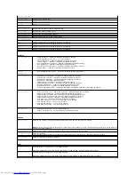
Processor Information 

Processor Type 

Displays the processor type 

L2 Cache 

Displays the L2 cache size 

L3 Cache 

Displays the L3 cache size 

Memory Information 

Memory Installed 

Indicates the amount of memory installed in MB 

Memory Speed 

Indicates the memory speed in MHz 

Memory Technology 

Indicates the type of installed memory 

Memory Channel 

Indicates single channel or dual channel mode 

Device Information 

SATA 0 

Displays the SATA drive connected to the SATA 0 connector 

SATA 1 

Displays the SATA drive connected to the SATA 1 connector 

SATA 2 

Displays the SATA drive connected to the SATA 2 connector 

SATA 3 

Displays the SATA drive connected to the SATA 3 connector 


Advanced


CPU Configuration 

l


Hyper-threading 

 Enabled or Disabled (Enabled by default) 

l


Active Processor Cores 

 All; 1; 2; 3 (All by default) 

l


Limit CPUID Value 

 Enabled or Disabled (Disabled by default) 

l


CPU XD Support 

 Enabled or Disabled (Enabled by default) 

l


Intel Virtualization Technology 

 Enabled or Disabled (Enabled by default) 

l


Intel SpeedStep 

 Enabled or Disabled (Enabled by default) 

l


Intel Turbo Boost Technology 

 Enabled or Disabled (Enabled by default) 

l


CPU C6 Report 

 Enabled or Disabled (Enabled by default) 

Graphics 

Configuration 

l


Intel Multiple Monitor Feature 

 Enabled or Disabled (Disabled by default) 

System Configuration 

l


Onboard Audio Controller 

 Enabled or Disabled (Enabled by default) 

l


Onboard LAN Controller 

 Enabled or Disabled (Enabled by default) 

l


Onboard LAN Boot ROM 

 Enabled or Disabled (Disabled by default) 

l


SATA Mode 

 AHCI; RAID (AHCI by default) 

l


USB Controller 

 Enabled or Disabled (Enabled by default) 

l


USB Storage Boot Function 

 Enabled or Disabled (Enabled by default) 

l


Onboard Card Reader 

 Enabled or Disabled (Enabled by default) 

l


Onboard Serial Port 

 Enabled or Disabled (Enabled by default) 

l


Serial Port IO Address/IRQ 

 3F8h/IRQ4, 2F8h/IRQ3, 3E8h/IRQ4, 2E8h/IRQ3 (3F8h/IRQ4 by default) 

Power Management 

l


Restore AC Power Loss 

 Power Off; Power On; Last State (Power Off by default) 

l


Wake on LAN from S4/S5 

 Enabled or Disabled (Disabled by default) 

l


USB Powershare in S4/S5 State 

Enabled or Disabled (Disabled by default) 

l


USB Powershare in Sleep State 

 Normal; Enhanced (Normal by default) 

l


Resume by PS/2 Devices 

 Enabled or Disabled (Enabled by default) 

l


Auto Power On 

 Enabled or Disabled (Disabled by default) 

l


Auto Power On Date 

 0 to 31, 0 for everyday (15 by default) 

l


Auto Power On Hour 

 0 to 23 (12 by default) 

l


Auto Power On Minute 

 0 to 59 (30 by default) 

l


Auto Power On Second 

 0 to 59 (30 by default) 

Post Behavior 

l


Bootup NumLock State 

 On; Off (On by default) 

l


Keyboard Error Report 

 Enabled; Disabled (Enabled by default) 


Security 


Admin Password 

Allows to set, change, or delete the administrator password when the service tag is present 


NOTE: 

Deleting the administrator password will delete the system password. Hence, the administrator password must be set before 

setting the system password. 

System Password 

Allows to set, change, or delete the system password when the service tag is present 

Boot Menu Security 

Enabled or Disabled 
User must enter Admin Password to access the F12 Boot Menu when this setting is enabled (Disabled by default) 

HDD Protection 

Feature 

Enabled or Disabled (Disabled by default) 


Boot


1st Boot Priority 

Specifies the boot sequence from the available devices 

Hard Disk; CD/DVD; Network; USB Floppy; USB Hard Disk; USB CD/DVD; Disabled (Hard Disk by default) 

2nd Boot Priority 

Specifies the boot sequence from the available devices 

Hard Disk; CD/DVD; Network; USB Floppy; USB Hard Disk; USB CD/DVD; Disabled (CD/DVD Drive by default) 

Summary of Contents for Inspiron 620s

Page 1: ...cument to refer to either the entities claiming the marks and names or their products Dell Inc disclaims any proprietary interest in trademarks and trade names other than its own 2011 05 Rev A00 Regulatory model D06D series Regulatory type D06D001 Technical Overview Before You Begin Computer Cover Memory Module s Front Bezel PCI Express Cards Card Retention Bracket Drives Front I O Panel Power But...

Page 2: ...hen you shut down the operating system press and hold the power button until the computer turns off Safety Instructions Use the following safety guidelines to help protect your computer from potential damage and to help ensure your own personal safety 1 Ensure that the work surface is flat and clean to prevent the computer cover from being scratched CAUTION To avoid losing data save and close all ...

Page 3: ...m the Media Card Reader 7 Press and hold the power button to ground the system board Back to Contents Page CAUTION To disconnect a network cable first unplug the cable from your computer and then unplug the cable from the network device CAUTION Before touching anything inside your computer ground yourself by touching an unpainted metal surface such as the metal at the back of the computer While yo...

Page 4: ...ecure location WARNING Before working inside your computer read the safety information that shipped with your computer For additional safety best practices information see the Regulatory Compliance Homepage at www dell com regulatory_compliance WARNING To guard against electrical shock always unplug your computer from the electrical outlet before removing the cover WARNING Do not operate your comp...

Page 5: ...zel clamps into the front panel slots 3 Rotate the front bezel towards the computer until the front bezel tabs snap into place 4 Replace the computer cover see Replacing the Computer Cover Back to Contents Page 1 front bezel 2 front bezel tabs 3 3 front bezel clamps 4 4 front panel slots 4 5 front panel ...

Page 6: ...in the Select Your Product Line list d Select the product model number in the Select Your Product Model list e Click Confirm 4 A list of results appears on the screen Click BIOS 5 Click Download Now to download the latest BIOS file The File Download window appears 6 Click Save to save the file on your desktop The file downloads to your desktop 7 Click Close if the Download Complete window appears ...

Page 7: ...ructions based on the type of securing tab on the PCI Express x16 card slot l Push the securing tab to the side grasp the card by its top corners and then ease it out of the connector WARNING Before working inside your computer read the safety information that shipped with your computer For additional safety best practices information see the Regulatory Compliance Homepage at dell com regulatory_c...

Page 8: ...r otherwise customizing it for your computer 3 Connect the PCI Express card to the card slot PCI Express x1 card Place the PCI Express card in the slot on the system board and press down firmly Ensure that the PCI Express card is fully seated in the slot 1 securing tab 2 PCI Express x16 card slot 3 PCI Express x16 card 1 securing tab 2 PCI Express x16 card slot 3 PCI Express x16 card 1 securing ta...

Page 9: ... the slot on the system board and press down firmly Ensure that the PCI Express card is fully seated in the slot l Place the PCI Express card in the slot on the system board and press down firmly Ensure that the PCI Express card is fully seated in the slot 1 PCI Express x1 card 2 PCI Express x1 card slot 1 securing tab 2 PCI Express x16 card slot 3 PCI Express x16 card 1 securing tab 2 PCI Express...

Page 10: ... or cause damage to the equipment NOTE For information about the location of external connectors see the Setup Guide For information on installing drivers and software for your card see the documentation that shipped with the card Installed Removed Sound card 1 Enter system setup see System Setup 2 Go to Onboard Audio Controller and then change the setting to Disabled 3 Connect the external audio ...

Page 11: ...eplace the computer cover see Replacing the Computer Cover WARNING Before working inside your computer read the safety information that shipped with your computer For additional safety best practices information see the Regulatory Compliance Homepage at dell com regulatory_compliance WARNING To guard against electrical shock always unplug your computer from the electrical outlet before removing th...

Page 12: ...Back to Contents Page 1 release tab 2 card retention bracket ...

Page 13: ...tices information see the Regulatory Compliance Homepage at www dell com regulatory_compliance WARNING A new battery can explode if it is incorrectly installed Replace the battery only with the same or equivalent type recommended by the manufacturer Discard used batteries according to the manufacturer s instructions WARNING To guard against electrical shock always unplug your computer from the ele...

Page 14: ... the Computer Cover 4 Connect your computer and devices to electrical outlets and then turn them on 5 Enter system setup see System Setup and restore the settings you recorded in step 1 Back to Contents Page 1 coin cell battery 2 battery socket ...

Page 15: ...computer cover with the slots located along the edge of the chassis WARNING Before working inside your computer read the safety information that shipped with your computer For additional safety best practices information see the Regulatory Compliance Homepage at www dell com regulatory_compliance WARNING To guard against likelihood of electric shock laceration by moving fan blades or other unexpec...

Page 16: ... slide it towards the front of the computer 6 Using a screwdriver replace the two screws that secure the computer cover to the chassis 7 Place the computer in an upright position Back to Contents Page 1 computer cover 2 screws 2 3 slots ...

Page 17: ...rd against electrical shock always unplug your computer from the electrical outlet before removing the cover WARNING Do not operate your equipment with any cover s including computer covers bezels filler brackets front panel inserts etc removed CAUTION Only a certified service technician should perform repairs on your computer Damage due to servicing that is not authorized by Dell is not covered b...

Page 18: ... and place it under the tab on the processor cover 1 processor 2 socket CAUTION Ground yourself by touching an unpainted metal surface at the back of the computer CAUTION When replacing the processor do not touch any of the pins inside the socket or allow any objects to fall on the pins in the socket CAUTION You must position the processor correctly in the socket to avoid permanent damage to the p...

Page 19: ...he Computer Cover 12 Connect your computer and devices to electrical outlets and turn them on Back to Contents Page 1 alignment post 2 tab 3 processor cover 4 release lever 5 processor 6 processor cover notch CAUTION Ensure that you apply new thermal grease New thermal grease is critical for ensuring adequate thermal bonding which is a requirement for optimal processor operation CAUTION Ensure tha...

Page 20: ... your computer from the electrical outlet before removing the cover WARNING Do not operate your computer with any cover s including computer covers bezels filler brackets front panel inserts etc removed CAUTION Only a certified service technician should perform repairs on your computer Damage due to servicing that is not authorized by Dell is not covered by your warranty CAUTION If you are replaci...

Page 21: ... bezel outwards and lift the hard drive off the hard drive bezel Replacing the Hard Drive Bezel 1 Follow the instructions in Before You Begin 2 Pull the tabs on the hard drive bezel outwards and place the hard drive in the hard drive bezel 3 Ensure the pins on the hard drive bezel are seated correctly into the pin holes on the hard drive 4 Replace the hard drive assembly see Replacing the Hard Dri...

Page 22: ...e for instructions on installing any software required for drive operation 9 Check the System Setup for drive configuration changes see System Setup Optical Drive Removing the Optical Drive 1 Follow the instructions in Before You Begin 2 Remove the computer cover see Removing the Computer Cover 3 Remove the front bezel see Removing the Front Bezel 4 Disconnect the power and data cables from the op...

Page 23: ...r until it snaps into position 4 Connect the power and data cables to the optical drive 5 Replace the front bezel see Replacing the Front Bezel 6 Replace the computer cover see Replacing the Computer Cover 7 Connect your computer and devices to electrical outlets and turn them on 8 See the documentation that shipped with the drive for instructions on installing any software required for drive oper...

Page 24: ...sis 3 Replace the four screws that secure the chassis fan to the chassis WARNING Before working inside your computer read the safety information that shipped with your computer For additional safety best practices information see the Regulatory Compliance Homepage at www dell com regulatory_compliance WARNING To guard against electrical shock always unplug your computer from the electrical outlet ...

Page 25: ...llow the instructions in Before You Begin 2 Clean the thermal grease from the bottom of the heat sink 3 Apply new thermal grease to the top of the processor 4 Place the processor fan and heat sink assembly over the processor WARNING Despite having a plastic shield the processor fan and heat sink assembly may be very hot during normal operation Ensure that it has had sufficient time to cool before ...

Page 26: ...heat sink assembly to the system board 7 Connect the processor fan cable to the system board connector FAN_CPU see System Board Components 8 Replace the computer cover see Replacing the Computer Cover 9 Connect your computer and devices to electrical outlets and turn them on Back to Contents Page NOTE Ensure that the processor fan and heat sink assembly is correctly seated and secure ...

Page 27: ...hipped with your computer For additional safety best practices information see the Regulatory Compliance Homepage at www dell com regulatory_compliance WARNING To guard against electrical shock always unplug your computer from the electrical outlet before removing the cover WARNING Do not operate your computer with any cover s including computer covers bezels filler brackets front panel inserts et...

Page 28: ...anel cables to the system board connectors AUDIOF1 USBF1 and USBF2 see System Board Components 5 Replace the front bezel see Replacing the Front Bezel 6 Replace the computer cover see Replacing the Computer Cover 7 Connect your computer and devices to electrical outlets and turn them on Back to Contents Page CAUTION To avoid damage to the cable connectors and the cable routing clips carefully slid...

Page 29: ...al safety best practices information see the Regulatory Compliance Homepage at www dell com regulatory_compliance WARNING To guard against electrical shock always unplug your computer from the electrical outlet before removing the cover WARNING Do not operate your computer with any cover s including computer covers bezels filler brackets front panel inserts etc removed CAUTION Only a certified ser...

Page 30: ...and then turn them on If a message appears stating that the memory size has changed press F1 to continue 7 Log on to your computer To verify that the memory is installed correctly click Start Control Panel System Check the amount of memory RAM listed Back to Contents Page 1 cutouts 2 2 tab 3 notch 4 memory module CAUTION To avoid damage to the memory module press the memory module straight down in...

Page 31: ...w holes on the power supply with the screw holes on the chassis WARNING Before working inside your computer read the safety information that shipped with your computer For additional safety best practices information see the Regulatory Compliance Homepage at www dell com regulatory_compliance WARNING To guard against electrical shock always unplug your computer from the electrical outlet before re...

Page 32: ... the chassis 5 Connect the DC power cables to the system board and drives see System Board Components 6 Replace the computer cover see Replacing the Computer Cover 7 Connect your computer and devices to electrical outlets and turn them on Back to Contents Page ...

Page 33: ...ule 1 Follow the instructions in Before You Begin 2 Align and push the power button module tabs into the slots on the front panel WARNING Before working inside your computer read the safety information that shipped with your computer For additional safety best practices information see the Regulatory Compliance Homepage at www dell com regulatory_compliance WARNING To guard against electrical shoc...

Page 34: ...d connector LEDH1 see System Board Components 4 Replace the front bezel see Replacing the Front Bezel 5 Replace the computer cover see Replacing the Computer Cover 6 Connect your computer and devices to electrical outlets and turn them on Back to Contents Page ...

Page 35: ...ct all cables connected to the system board see System Board Components Note the routing of all cables as you remove them so that you can re route them correctly after installing the new system board 8 Remove the six screws that secure the system board to the chassis WARNING Before working inside your computer read the safety information that shipped with your computer For additional safety best p...

Page 36: ...cing the Computer Cover 10 Connect your computer and devices to electrical outlets and turn them on 11 Flash the system BIOS as needed see Flashing the BIOS 12 Enter the service tag see Entering the Service Tag in the BIOS Entering the Service Tag in the BIOS 1 Turn on the computer 2 Press F2 during POST to enter the system setup program 3 From the main tab enter the service tag in the Set Service...

Page 37: ...down your computer see Turning Off Your Computer and try again Setup Item This field appears on the left side of the system setup window The field is a scrollable list containing features that define the configuration of your computer including installed hardware power conservation and security features Scroll up and down the list with the up and down arrow keys As an option is highlighted the Hel...

Page 38: ...nboard Card Reader Enabled or Disabled Enabled by default l Onboard Serial Port Enabled or Disabled Enabled by default l Serial Port IO Address IRQ 3F8h IRQ4 2F8h IRQ3 3E8h IRQ4 2E8h IRQ3 3F8h IRQ4 by default Power Management l Restore AC Power Loss Power Off Power On Last State Power Off by default l Wake on LAN from S4 S5 Enabled or Disabled Disabled by default l USB Powershare in S4 S5 State En...

Page 39: ...ot Device Menu appears listing all available boot devices 4 On the Boot Device Menu choose the device you want to boot from For example if you are booting to a USB memory key highlight USB Storage Device and press Enter Changing Boot Sequence for Future Boots 1 Enter system setup see Entering System Setup 2 Use the arrow keys to highlight the Boot menu option and press Enter to access the menu 3rd...

Page 40: ...computer cover see Replacing the Computer Cover 9 Connect your computer and devices to electrical outlets and turn them on Clearing CMOS Passwords NOTE Write down your current boot sequence in case you want to restore it WARNING Before you begin any of the procedures in this section follow the safety instructions that shipped with your computer WARNING The computer must be disconnected from the el...

Page 41: ...and 3 7 Replace the computer cover see Replacing the Computer Cover 8 Connect your computer and devices to electrical outlets and turn them on Back to Contents Page WARNING The computer must be disconnected from the electrical outlet to clear the password setting CAUTION Only a certified service technician should perform repairs on your computer Damage due to servicing that is not authorized by De...

Page 42: ...ices information see the Regulatory Compliance Homepage at www dell com regulatory_compliance WARNING To avoid electrostatic discharge ground yourself by using a wrist grounding strap or by periodically touching an unpainted metal surface such as a connector on your computer CAUTION Only a certified service technician should perform repairs on your computer Damage due to servicing that is not auth...

Page 43: ...connector SATA 2 10 chassis fan connector FAN_SYS1 11 SATA drive connector SATA 1 12 SATA drive connector SATA 0 13 SATA drive connector SATA 3 14 CMOS reset jumper CMOSCLR1 15 front panel USB connector USBF2 16 front panel USB connector USBF1 17 password reset jumper PSWDCLR1 18 front panel audio connector AUDIOF1 19 PCI Express x1 card slot SLOT4 20 PCI Express x1 card slot SLOT3 21 PCI Express ...

Reviews: