Back to Contents Page
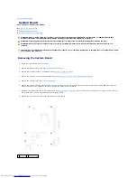
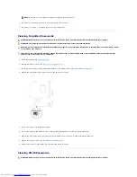
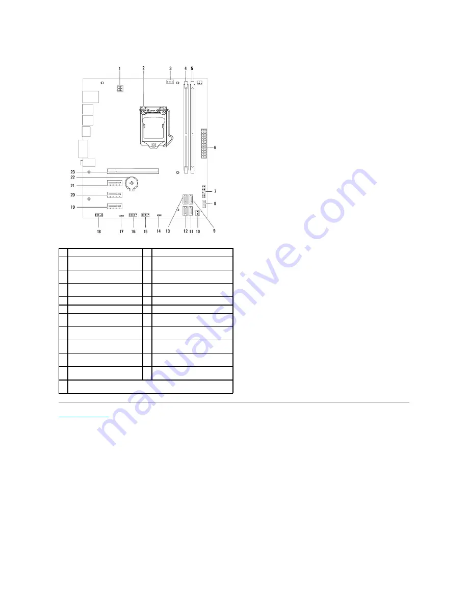
1
power connector (ATX12V)
2
processor socket
3
processor fan connector
(FAN_CPU)
4
memory module connector (DIMM1)
5
memory module connector
(DIMM2)
6
main power connector
(ATX)
7
power button connector
(LEDH1)
8
internal speaker connector
(INTSPKR1)
9
SATA drive connector (SATA 2)
10 chassis fan connector (FAN_SYS1)
11 SATA drive connector (SATA 1)
12 SATA drive connector (SATA 0)
13 SATA drive connector
(SATA 3)
14 CMOS reset jumper (CMOSCLR1)
15 front panel USB connector
(USBF2)
16 front panel USB connector (USBF1)
17 password reset jumper
(PSWDCLR1)
18 front panel audio connector
(AUDIOF1)
19 PCI Express x1 card slot
(SLOT4)
20 PCI Express x1 card slot
(SLOT3)
21 PCI Express x1 card slot
(SLOT2)
22 battery socket
(BT1)
23 PCI Express x16 card slot
(SLOT1)


