background image

Removing the power button with fingerprint

reader

NOTE:

 Before working inside your computer, read the safety information that shipped with your computer and follow

the steps in 

Before working inside your computer

. After working inside your computer, follow the instructions in 

After

working inside your computer

. For more safety best practices, see the Regulatory Compliance home page at 

www.dell.com/

regulatory_compliance

.

Prerequisites

1. Remove the 

base cover

.

2. Remove the 

battery

.

3. Remove the 

memory modules

.

4. Remove the 

solid-state drive

.

5. Remove the 

hard drive

.

6. Remove the 

coin-cell battery

.

7. Remove the 

wireless card

.

8. Remove the 

speakers

.

9. Remove the 

fan

.

10. Remove the 

display assembly

.

11. Remove the 

I/O board

.

12. Remove the 

system board

.

Procedure

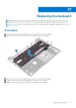
1. Follow the procedure from step 1 to step 5 in "

Removing the keyboard

".

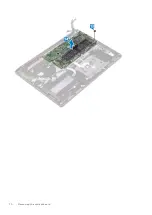
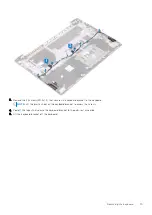
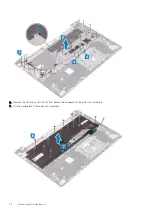
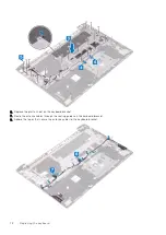
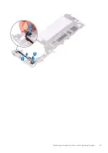
2. Slide and remove the power button with fingerprint-reader cable from the keyboard bracket.
3. Peel the power button with fingerprint-reader cable from the keyboard bracket.
4. Lift the power button with fingerprint-reader, along with its cable, off the slot

38

80

Removing the power button with fingerprint reader

Summary of Contents for Inspiron 7590 2in1

Page 1: ...Inspiron 7590 2in1 Service Manual Regulatory Model P84F Regulatory Type P84F001 July 2021 Rev A03 ...

Page 2: ...tial damage to hardware or loss of data and tells you how to avoid the problem WARNING A WARNING indicates a potential for property damage personal injury or death 2019 2021 Dell Inc or its subsidiaries All rights reserved Dell EMC and other trademarks are trademarks of Dell Inc or its subsidiaries Other trademarks may be trademarks of their respective owners ...

Page 3: ...Procedure 15 Chapter 7 Replacing the base cover 18 Procedure 18 Chapter 8 Removing the battery 20 Lithium ion battery precautions 20 Prerequisites 20 Procedure 20 Chapter 9 Replacing the battery 23 Lithium ion battery precautions 23 Procedure 23 Post requisites 24 Chapter 10 Removing the memory modules 25 Prerequisites 25 Procedure 25 Chapter 11 Replacing the memory modules 27 Procedure 27 Post re...

Page 4: ...fan 40 Procedure 40 Post requisites 40 Chapter 20 Removing the solid state drive 41 Prerequisites 41 Procedure to remove M 2 2230 solid state drive 41 Procedure to remove M 2 2280 solid state drive 42 Chapter 21 Replacing the solid state drive 43 Procedure to replace M 2 2230 solid state drive 43 Procedure to replace M 2 2280 solid state drive 44 Post requisites 45 Chapter 22 Removing the coin cel...

Page 5: ...rs 60 Procedure 60 Post requisites 60 Chapter 30 Removing the heat sink 61 Prerequisites 61 Procedure 61 Chapter 31 Replacing the heat sink 62 Procedure 62 Post requisites 62 Chapter 32 Removing the display assembly 63 Prerequisites 63 Procedure 63 Chapter 33 Replacing the display assembly 65 Procedure 65 Post requisites 66 Chapter 34 Removing the system board 67 Prerequisites 67 Procedure 67 Chap...

Page 6: ...r 42 Device drivers 88 Intel Chipset Software Installation Utility 88 Video drivers 88 Intel Serial IO driver 88 Intel Trusted Execution Engine Interface 88 Intel Virtual Button driver 88 Wireless and Bluetooth drivers 88 Chapter 43 System setup 89 BIOS overview 89 Entering BIOS setup program 89 Navigation keys 89 Boot Sequence 89 System setup options 90 System and admin password 97 Assigning a sy...

Page 7: ... built in self test L BIST 102 Display panel built in self test LCD BIST 103 Outcome 103 Dell SupportAssist Pre boot System Performance Check diagnostics 104 SupportAssist diagnostics 104 System diagnostic lights 104 Recovering the operating system 105 Backup media and recovery options 105 Drain residual flea power perform hard reset 105 WiFi power cycle 106 Contents 7 ...

Page 8: ... Start Power Shut down NOTE If you are using a different operating system see the documentation of your operating system for shut down instructions 3 Disconnect your computer and all attached devices from their electrical outlets 4 Disconnect all attached network devices and peripherals such as keyboard mouse and monitor from your computer 5 Remove any media card and optical disc from your compute...

Page 9: ...y screws remain inside your computer 2 Connect any external devices peripherals or cables you removed before working on your computer 3 Replace any media cards discs or any other parts that you removed before working on your computer 4 Connect your computer and all attached devices to their electrical outlets 5 Turn on your computer 2 After working inside your computer 9 ...

Page 10: ...ll tab not the cable itself Some cables have connectors with locking tabs or thumbscrews that you must disengage before disconnecting the cable When disconnecting cables keep them evenly aligned to avoid bending the connector pins When connecting cables ensure that the ports and the connectors are correctly oriented and aligned CAUTION Press and eject any installed card from the media card reader ...

Page 11: ...ng wire Never use wireless wrist straps Always be aware that the internal wires of a wrist strap are prone to damage from normal wear and tear and must be checked regularly with a wrist strap tester in order to avoid accidental ESD hardware damage It is recommended to test the wrist strap and bonding wire at least once per week ESD Wrist Strap Tester The wires inside of an ESD strap are prone to d...

Page 12: ...bags for safe transport Lifting equipment Adhere to the following guidelines when lifting heavy weight equipment CAUTION Do not lift greater than 50 pounds Always obtain additional resources or use a mechanical lifting device 1 Get a firm balanced footing Keep your feet apart for a stable base and point your toes out 2 Tighten stomach muscles Abdominal muscles support your spine when you lift offs...

Page 13: ...Recommended tools The procedures in this document may require the following tools Philips screwdriver 1 Flat head screwdriver Plastic scribe 4 Recommended tools 13 ...

Page 14: ... Screw type Quantity Screw image Base cover Palm rest assembly M2x4 7 Battery Palm rest assembly M2x3 2 Fan Palm rest assembly M2x3 2 Hard drive assembly Palm rest assembly M2x3 3 Hard drive bracket Hard drive M3x3 4 Display hinges Palm rest assembly M2 5x4 4 I O board Palm rest assembly M2x4 1 Keyboard Palm rest assembly M1 2x1 5 19 Keyboard bracket Palm rest assembly M1 2x1 8 24 Power adapter po...

Page 15: ...home page at www dell com regulatory_compliance Procedure 1 Loosen the two captive screws that secure the base cover to the palm rest assembly 2 Remove the seven screws M2x4 that secure the base cover to the palm rest assembly 3 Using a plastic scribe pry the base cover from the tabs on the hinges and continue to pry the base cover from the slots on the palm rest assembly CAUTION Do not pry the ba...

Page 16: ...NOTE Disconnect the battery cable only when you continue to remove other components from your computer 5 Disconnect the battery cable from the system board 16 Removing the base cover ...

Page 17: ...Removing the base cover 17 ...

Page 18: ...ur computer follow the instructions in After working inside your computer For more safety best practices see the Regulatory Compliance home page at www dell com regulatory_compliance Procedure 1 Connect the battery cable to the system board if applicable 2 Align the tabs on the base cover with the slots on the palm rest assembly and snap the base cover to the palm rest assembly 7 18 Replacing the ...

Page 19: ...3 Replace the seven screws M2x4 that secure the base cover to the palm rest assembly 4 Tighten the two captive screws that secure the base cover to the palm rest assembly Replacing the base cover 19 ...

Page 20: ...attery Do not use tools of any kind to pry on or against the battery Ensure any screws during the servicing of this product are not lost or misplaced to prevent accidental puncture or damage to the battery and other system components If the battery gets stuck inside your computer as a result of swelling do not try to release it as puncturing bending or crushing a lithium ion battery can be dangero...

Page 21: ...5 Turn the computer over open the display and then press and hold the power button for five seconds to ground the system board Removing the battery 21 ...

Page 22: ...22 Removing the battery ...

Page 23: ...he battery Do not bend the battery Do not use tools of any kind to pry on or against the battery Ensure any screws during the servicing of this product are not lost or misplaced to prevent accidental puncture or damage to the battery and other system components If the battery gets stuck inside your computer as a result of swelling do not try to release it as puncturing bending or crushing a lithiu...

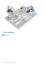
Page 24: ...Post requisites Replace the base cover 24 Replacing the battery ...

Page 25: ...rking inside your computer For more safety best practices see the Regulatory Compliance home page at www dell com regulatory_compliance Prerequisites Remove the base cover Procedure 1 Lift the flap to access the memory module 2 Use your fingertips to carefully spread apart the securing clips on each end of the memory module slot until the memory module pops up 3 Slide and remove the memory module ...

Page 26: ...26 Removing the memory modules ...

Page 27: ... For more safety best practices see the Regulatory Compliance home page at www dell com regulatory_compliance Procedure 1 Lift the flap to access the memory module slot 2 Align the notch on the memory module with the tab on the memory module slot 3 Slide the memory module firmly at an angle into the memory module slot 4 Press the memory module down until it clicks into place NOTE If you do not hea...

Page 28: ...Post requisites Replace the base cover 28 Replacing the memory modules ...

Page 29: ...best practices see the Regulatory Compliance home page at www dell com regulatory_compliance Prerequisites Remove the base cover Procedure 1 Locate the wireless card on the system board 2 Remove the screw M2x3 that secures the wireless card bracket to the wireless card and palm rest assembly 3 Remove the wireless card bracket from the wireless card 4 Disconnect the antenna cables from the wireless...

Page 30: ...30 Removing the wireless card ...

Page 31: ...ntenna cables to the wireless card The following table provides the antenna cable color scheme for the wireless card that is supported by your computer Table 2 Antenna cable color scheme Connectors on the wireless card Antenna cable color Main white triangle White Auxiliary black triangle Black 2 Align the notch on the wireless card with the tab on the wireless card slot and insert the wireless ca...

Page 32: ...Post requisites Replace the base cover 32 Replacing the wireless card ...

Page 33: ...e the Regulatory Compliance home page at www dell com regulatory_compliance Prerequisites Remove the base cover Procedure 1 Remove the two screws M2 5x4 that secure the left display hinge to the system board 2 Lift the left display hinge from the system board 3 Disconnect the power adapter port cable from the system board 4 Remove the screw M2x3 that secures the power adapter port to the palm rest...

Page 34: ...t practices see the Regulatory Compliance home page at www dell com regulatory_compliance Procedure 1 Place the power adapter port into the slot on the palm rest assembly 2 Replace the screw M2x3 that secures the power adapter port to the palm rest assembly 3 Connect the power adapter port cable to the system board 4 Close the left display hinge 5 Replace the two screws M2 5x4 that secure the left...

Page 35: ...ulatory_compliance Prerequisites Remove the base cover Procedure 1 Using the pull tab disconnect the I O board cable from the I O board 2 Open the latch and disconnect the fingerprint reader cable from the I O board 3 Disconnect the coin cell battery cable from the I O board 4 Remove the two screws M2 5x4 that secure the right display hinge to the I O board 5 Lift the right display hinge from the ...

Page 36: ...36 Removing the I O board ...

Page 37: ...edure 1 Slide the I O board into the slots on the palm rest assembly 2 Align the screw hole on the I O board with the screw hole on the palm rest assembly and replace the screw M2x3 that secures the I O board to the palm rest assembly 3 Close the right display hinge 4 Replace the two screws M2 5x4 that secure the right display hinge to the I O board 5 Connect the coin cell battery cable to the I O...

Page 38: ...Post requisites Replace the base cover 38 Replacing the I O board ...

Page 39: ...uter follow the instructions in After working inside your computer For more safety best practices see the Regulatory Compliance home page at www dell com regulatory_compliance Prerequisites Remove the base cover Procedure 1 Disconnect the fan cable from the system board 2 Remove the two screws M2x3 that secure the fan to the palm rest assembly 3 Lift the fan off the palm rest assembly 18 Removing ...

Page 40: ...he instructions in After working inside your computer For more safety best practices see the Regulatory Compliance home page at www dell com regulatory_compliance Procedure 1 Using the alignment posts place the fan on the palm rest assembly 2 Replace the two screws M2x3 that secure the fan to the palm rest assembly 3 Connect the fan cable to the system board Post requisites Replace the base cover ...

Page 41: ...rives are fragile Exercise care when handling the solid state drive CAUTION To avoid data loss do not remove the solid state drive while the computer is in sleep or on state Prerequisites Remove the base cover Procedure to remove M 2 2230 solid state drive 1 Remove the two screws M2x3 that secure the solid state drive to the palm rest assembly 2 Slide and remove the solid state drive bracket from ...

Page 42: ...ive Intel Optane storage module shield to the palm rest assembly 2 Slide and remove the solid state drive Intel Optane storage module shield from the solid state drive slot 3 Slide and remove the solid state drive Intel Optane storage module from the solid state drive slot 42 Removing the solid state drive ...

Page 43: ...lid state drive Procedure to replace M 2 2230 solid state drive 1 Align the notch on the solid state drive with the tab on the solid state drive slot 2 Slide the solid state drive firmly into the solid state drive slot at an angle 3 Press the other end of the solid state drive and replace the screw M2x3 that secures the solid state drive to the palm rest assembly 4 Slide the solid state drive brac...

Page 44: ...e firmly into the solid state drive slot at an angle 3 Slide the solid state drive Intel Optane storage module shield firmly into the solid state drive slot at an angle Secure the tab on the solid state drive slot with the slot on the solid state drive bracket 4 Replace the two screws M2x3 that secure the solid state drive Intel Optane storage module shield to the palm rest assembly 44 Replacing t...

Page 45: ...Post requisites Replace the base cover Replacing the solid state drive 45 ...

Page 46: ...re safety best practices see the Regulatory Compliance home page at www dell com regulatory_compliance CAUTION Removing the coin cell battery resets the BIOS setup program s settings to default It is recommended that you note the BIOS setup program s settings before removing the coin cell battery Prerequisites Remove the base cover Procedure 1 Disconnect the coin cell battery cable from the I O bo...

Page 47: ... working inside your computer follow the instructions in After working inside your computer For more safety best practices see the Regulatory Compliance home page at www dell com regulatory_compliance Procedure 1 Adhere the coin cell battery to the palm rest assembly 2 Connect the coin cell battery cable to the I O board Post requisites Replace the base cover 23 Replacing the coin cell battery 47 ...

Page 48: ...y information that shipped with your computer and follow the steps in Before working inside your computer After working inside your computer follow the instructions in After working inside your computer For more safety best practices see the Regulatory Compliance home page at www dell com regulatory_compliance Prerequisites 1 Remove the base cover 2 Remove the battery Procedure 1 Open the latch an...

Page 49: ... the hard drive cable from the system board 2 Remove the three screws M2x3 that secure the hard drive assembly to the palm rest assembly 3 Lift the hard drive assembly along with its cable off the palm rest assembly Removing the hard drive 49 ...

Page 50: ...nect the interposer from the hard drive assembly 5 Remove the four screws M3x3 that secure the hard drive bracket to the hard drive 6 Lift the hard drive off of the hard drive bracket 50 Removing the hard drive ...

Page 51: ...Removing the hard drive 51 ...

Page 52: ...fety best practices see the Regulatory Compliance home page at www dell com regulatory_compliance CAUTION Hard drives are fragile Exercise care when handling the hard drive Procedure 1 Place the hard drive into the hard drive bracket 2 Align the screw holes on the hard drive bracket with the screw holes on the hard drive and then replace the four screws M3x3 that secure the hard drive bracket to t...

Page 53: ...d drive assembly with the screw holes on the palm rest assembly 5 Replace the three screws M2x3 that secure the hard drive assembly to the palm rest assembly 6 Connect the hard drive cable to the system board Replacing the hard drive 53 ...

Page 54: ...he alignment posts on the palm rest assembly place the left speaker on the palm rest assembly 2 Route the speaker cable through the routing guides on the palm rest assembly and adhere the tape secures the speaker cable to the palm rest assembly 3 Using the alignment posts on the palm rest assembly place the right speaker on the palm rest assembly 4 Adhere the tapes that secure the speaker cable to...

Page 55: ...gulatory_compliance Procedure 1 Open the latch and disconnect the touchpad cable from the system board 2 Peel off the tapes that secure the touchpad assembly to the palm rest assembly 3 Peel off the tape that secures the speaker cable to the touchpad bracket 4 Remove the three screws M2x3 that secure the touchpad bracket to the palm rest assembly 5 Lift the touchpad bracket off the palm rest assem...

Page 56: ...56 Removing the touchpad ...

Page 57: ... touchpad into the slot on the palm rest assembly 2 Replace the two screws M1 6x2 that secure the touchpad to the palm rest assembly 3 Align the screw holes on the touchpad bracket with the screw holes on the palm rest assembly 4 Replace the three screws M2x3 that secure the touchpad bracket to the palm rest assembly 5 Adhere the tape that secures the touchpad bracket to the palm rest assembly 6 A...

Page 58: ...58 Replacing the touchpad ...

Page 59: ...dell com regulatory_compliance Prerequisites 1 Remove the base cover 2 Remove the battery Procedure 1 Open the latch and disconnect the hard drive cable from the system board 2 Disconnect the speaker cable from the system board 3 Peel off the tapes and release the speaker cable from the routing guides on the palm rest assembly 4 Lift the right speaker from the palm rest assembly 5 Peel off the tap...

Page 60: ...e alignment posts on the palm rest assembly place the left speaker on the palm rest assembly 2 Route the speaker cable through the routing guides on the palm rest assembly and adhere the tape secures the speaker cable to the palm rest assembly 3 Using the alignment posts on the palm rest assembly place the right speaker on the palm rest assembly 4 Adhere the tapes that secure the speaker cable to ...

Page 61: ...compliance NOTE The heat sink may become hot during normal operation Allow sufficient time for the heat sink to cool before you touch it CAUTION For maximum cooling of the processor do not touch the heat transfer areas on the heat sink The oils in your skin can reduce the heat transfer capability of the thermal grease Prerequisites 1 Remove the base cover 2 Remove the fan Procedure 1 In reverse or...

Page 62: ...gulatory_compliance CAUTION Incorrect alignment of the heat sink can damage the system board and processor NOTE If either the system board or the heat sink is replaced use the thermal pad paste provided in the kit to ensure that thermal conductivity is achieved Procedure 1 Align the screw holes on the heat sink with the screw holes on the system board 2 In sequential order as indicated on the heat...

Page 63: ...Prerequisites 1 Remove the base cover 2 Remove the fan Procedure 1 Open the latch and disconnect the touchscreen board cable from the system board 2 Peel the tape to release the touchscreen board cable and remove the cable from the routing guides on the palm rest assembly 3 Using the pull tab disconnect the display cable from the system board 4 Peel the tape that secures the display cable to the s...

Page 64: ...n the computer over and remove the four screws M2 5x4 that secure the display hinges to the I O board and system board 7 Lift the display assembly off the palm rest assembly 64 Removing the display assembly ...

Page 65: ...e display assembly on the palm rest assembly Align the screw holes on the display hinges with the screw holes on the I O board and system board 2 Replace the four screws M2 5x4 that secure the display hinges to the I O board and system board 3 Close the display 4 Connect the display cable to the system board 5 Adhere the tape that secures the display cable to the system board 6 Route the touchscre...

Page 66: ...Post requisites 1 Replace the fan 2 Replace the base cover 66 Replacing the display assembly ...

Page 67: ...st make the appropriate changes again after you replace the system board NOTE Before disconnecting the cables from the system board note the location of the connectors so that you can reconnect the cables correctly after you replace the system board Prerequisites 1 Remove the base cover 2 Remove the battery 3 Remove the memory modules 4 Remove the solid state drive 5 Remove the wireless card 6 Rem...

Page 68: ... the system board 7 Open the latch and disconnect the keyboard cable from the system board 8 Open the latch and disconnect the touchpad cable from the system board 9 Disconnect the speaker cable from the system board 10 Open the latch and disconnect the hard drive cable from the system board 11 Using the pull tab disconnect the I O board cable from the system board 12 Open the latch and disconnect...

Page 69: ...13 Remove the two screws M2x2 that secure the system board to the palm rest assembly 14 Lift the system board off the palm rest assembly Removing the system board 69 ...

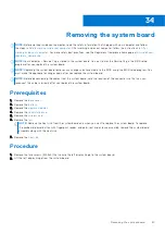
Page 70: ...70 Removing the system board ...

Page 71: ...the BIOS setup program after you replace the system board NOTE Replacing the system board removes any changes you have made to the BIOS using the BIOS setup program You must make the appropriate changes again after you replace the system board Procedure 1 Align the screw holes on the system board with the screw holes on the palm rest assembly 2 Replace the two screws M2x2 that secure the system bo...

Page 72: ... Slide the keyboard backlight cable to the system board and close the latch to secure the cable 10 Connect the power adapter port cable to the system board 11 Adhere the tape that secures the display cable to the system board 12 Connect the display cable to the system board 13 Close the left display hinge 14 Replace the two screws M2 5x4 that secure the left display hinge to the system board 72 Re...

Page 73: ... the base cover Entering the Service Tag in the BIOS setup program 1 Turn on or restart your computer 2 Press F2 when the Dell logo is displayed to enter the BIOS setup program 3 Navigate to the Main tab and enter the Service Tag in the Service Tag Input field NOTE Service tag is the alphanumeric identifier located at the back side of your computer Replacing the system board 73 ...

Page 74: ...atory_compliance Prerequisites 1 Remove the base cover 2 Remove the battery 3 Remove the memory modules 4 Remove the solid state drive 5 Remove the hard drive 6 Remove the coin cell battery 7 Remove the wireless card 8 Remove the speakers 9 Remove the fan 10 Remove the display assembly 11 Remove the I O board 12 Remove the power button with fingerprint reader 13 Remove the system board Procedure 1...

Page 75: ...yboard bracket to the keyboard NOTE Lift the plastic sheet on the keyboard bracket to access the screws 4 Peel off the tapes that secure the keyboard bracket to the palm rest assembly 5 Lift the keyboard bracket off the keyboard Removing the keyboard 75 ...

Page 76: ...6 Remove the 19 screws M1 2x1 5 that secure the keyboard to the palm rest assembly 7 Lift the keyboard off the palm rest assembly 76 Removing the keyboard ...

Page 77: ...e Regulatory Compliance home page at www dell com regulatory_compliance Procedure 1 Align the screw holes on the keyboard with the screw holes on the palm rest assembly 2 Replace the 19 screws M1 2x1 5 that secure the keyboard to palm rest assembly 3 Align the screws holes on the keyboard bracket with the screw holes on the keyboard 4 Adhere the tapes that secure the keyboard bracket to the palm r...

Page 78: ...plastic sheet on the keyboard bracket 7 Route the antenna cables through the routing guides on the keyboard bracket 8 Adhere the tapes that secure the antenna cables to the keyboard bracket 78 Replacing the keyboard ...

Page 79: ...he I O board 4 Replace the display assembly 5 Replace the fan 6 Replace the speakers 7 Replace the wireless card 8 Replace the coin cell battery 9 Replace the hard drive 10 Replace the solid state drive 11 Replace the memory modules 12 Replace the battery 13 Replace the base cover Replacing the keyboard 79 ...

Page 80: ... the battery 3 Remove the memory modules 4 Remove the solid state drive 5 Remove the hard drive 6 Remove the coin cell battery 7 Remove the wireless card 8 Remove the speakers 9 Remove the fan 10 Remove the display assembly 11 Remove the I O board 12 Remove the system board Procedure 1 Follow the procedure from step 1 to step 5 in Removing the keyboard 2 Slide and remove the power button with fing...

Page 81: ...Removing the power button with fingerprint reader 81 ...

Page 82: ...s see the Regulatory Compliance home page at www dell com regulatory_compliance Procedure 1 Place the fingerprint reader cable on the keyboard bracket 2 Adhere the fingerprint reader cable to the keyboard bracket 3 Slide and insert the power button with fingerprint reader cable on the slot on the keyboard bracket 4 Follow the procedure from step 3 to step 8 in Replacing the keyboard Post requisite...

Page 83: ...eplace the wireless card 7 Replace the coin cell battery 8 Replace the hard drive 9 Replace the solid state drive 10 Replace the memory modules 11 Replace the battery 12 Replace the base cover Replacing the power button with fingerprint reader 83 ...

Page 84: ...y_compliance Prerequisites 1 Remove the base cover 2 Remove the battery 3 Remove the memory modules 4 Remove the wireless card 5 Remove the power adapter port 6 Remove the I O board 7 Remove the fan 8 Remove the solid state drive 9 Remove the coin cell battery 10 Remove the hard drive 11 Remove the touch pad 12 Remove the speakers 13 Remove the display assembly 14 Remove the system board 15 Remove...

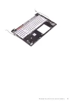
Page 85: ...Removing the palm rest and antenna assembly 85 ...

Page 86: ...instructions in After working inside your computer For more safety best practices see the Regulatory Compliance home page at www dell com regulatory_compliance Procedure Place the palm rest on a flat surface Post requisites 1 Replace the power button with fingerprint reader 2 Replace the keyboard 3 Replace the system board 4 Replace the display assembly 5 Replace the speakers 6 Replace the touch p...

Page 87: ...rive 10 Replace the I O board 11 Replace the power adapter port 12 Replace the wireless card 13 Replace the fan 14 Replace the memory modules 15 Replace the battery 16 Replace the base cover Procedure Place the palm rest on a flat surface Replacing the palm rest and antenna assembly 87 ...

Page 88: ...l com support Intel Trusted Execution Engine Interface In the Device Manager check if the Intel Trusted Execution Engine Interface driver is installed Install the driver update from www dell com support Intel Virtual Button driver In the Device Manager check if the Intel Virtual Button driver is installed Install the driver updates from www dell com support Wireless and Bluetooth drivers In the De...

Page 89: ...ss F2 immediately Navigation keys NOTE For most of the System Setup options changes that you make are recorded but do not take effect until you restart the system Keys Navigation Up arrow Moves to the previous field Down arrow Moves to the next field Enter Selects a value in the selected field if applicable or follow the link in the field Spacebar Expands or collapses a drop down list if applicabl...

Page 90: ...he ownership tag of the computer Signed Firmware Update Displays whether the signed firmware update is enabled Battery Displays the battery health information Primary Displays the primary battery Battery Level Displays the battery level Battery State Displays the battery state Health Displays the battery health AC Adapter Displays whether an AC adapter is installed Processor Information Processor ...

Page 91: ...he Bluetooth device information of the computer Table 4 System setup options Boot options menu Boot options Advanced Boot Options Enable UEFI Network Stack Enables or disables UEFI Network Stack Default OFF Boot Mode Boot Mode UEFI only Displays the boot mode of this computer Enable Boot Devices Enables or disables boot devices for this computer Boot Sequence Displays the boot sequence BIOS Setup ...

Page 92: ...isables various onboard devices Enable Camera Enables or disables the camera Default ON Keyboard Illumination Configures the operating mode of the keyboard illumination feature Default Disabled The keyboard illumination will always be off Keyboard Backlight Timeout on AC Configures the timeout value for the keyboard when an AC adapter is connected to the computer The keyboard backlight timeout val...

Page 93: ... disable the BIOS module interface of the optional Computrace R Service from Absolute Software Intel Platform Trust Technology On Enables or disables Platform Trust Technology PTT visibility to the operating system Default ON PPI Bypass for Clear Commands Enables or disables the operating system to skip BIOS Physical Presence Interface PPI user prompts when issuing the Clear command Default OFF Cl...

Page 94: ...om Mode Enables or disables the keys in the PK KEK db and dbx security key databases to be modified Default OFF Custom Mode Key Management Selects the custom values for expert key management Default PK Table 10 System setup options Performance menu Performance Intel Hyper Threading Technology Enables or disables the Intel Hyper Threading Technology to use processor resources more efficiently Defau...

Page 95: ...Sleep S3 mode in the operating system Default OFF NOTE If enabled the computer will not go to sleep Intel Rapid Start will be disabled automatically and the operating system power option will be blank if it was set to Sleep Enable USB Wake Support Enables the USB devices to wake the computer from Standby mode Default OFF Enable Intel Speed Shift Technology Enables or disables Intel Speed Shift Tec...

Page 96: ... Default OFF Warnings and Errors Selects an action on encountering a warning or error during boot Default Prompt on Warnings and Errors Stop prompt and wait for user input when warnings or errors are detected NOTE Errors deemed critical to the operation of the computer hardware will always halt the computer Table 14 System setup options Virtualization menu Virtualization Intel Virtualization Techn...

Page 97: ...FF Allow BIOS Downgrade Controls flashing of the system firmware to previous revisions Default ON Table 16 System setup options System Logs menu System Logs Power Event Log Displays Power events Default Keep BIOS Event Log Displays BIOS events Default Keep Thermal Event Log Displays Thermal events Default Keep Table 17 System setup options SupportAssist menu SupportAssist Dell Auto operating syste...

Page 98: ...o confirm 4 Press Esc and a message prompts you to save the changes 5 Press Y to save the changes The computer reboots Deleting or changing an existing system admin password To enter the System Setup press F2 immediately after a power on or reboot 1 In the System BIOS or System Setup screen select Passwords on the left pane The Passwords screen is displayed 2 Select System Password alter or delete...

Page 99: ...dows to download the latest BIOS setup program file 2 Create a bootable USB drive For more information see the knowledge base article 000145519 at www dell com support 3 Copy the BIOS setup program file to the bootable USB drive 4 Connect the bootable USB drive to the computer that needs the BIOS update 5 Restart the computer and press F12 6 Select the USB drive from the One Time Boot Menu 7 Type ...

Page 100: ...not boot if you turn off your computer 1 From a turn off state insert the USB drive where you copied the flash into a USB port of the computer 2 Turn on the computer and press F12 to access the One Time Boot Menu select BIOS Update using the mouse or arrow keys then press Enter The flash BIOS menu is displayed 3 Click Flash from file 4 Select external USB device 5 Select the file and double click ...

Page 101: ...he battery If a battery gets stuck in a device as a result of swelling do not try to free it as puncturing bending or crushing a battery can be dangerous Do not attempt to reassemble a damaged or swollen battery into a laptop Swollen batteries that are covered under warranty should be returned to Dell in an approved shipping container provided by Dell this is to comply with transportation regulati...

Page 102: ...er button to initiate M BIST 2 The battery status light illuminates in amber when there is a failure with the system board 3 Replace the system board to fix the issue NOTE The battery status LED will not illuminate if there is no failure present with the system board If further troubleshooting is required proceed with the applicable Guided Resolution for No Power No POST etc Display panel power ra...

Page 103: ... graphical anomalies 4 The computer reboot at the end of the last solid color Outcome The following table shows the outcome of running different types of BIST Table 20 BIST outcome M BIST Off No fault detected with system board Solid amber Indicates a problem with the system board Table 20 BIST outcome L BIST Off No fault detected with system board LED error code of 2 8 blinks Amber x2 then pause ...

Page 104: ... View status messages that indicate if the tests are completed successfully View error messages that indicate if problems were encountered during the test NOTE Some tests are meant for specific devices and require user interaction Ensure that you are present in front of the computer when the diagnostic tests are performed For more information see SupportAssist Pre Boot System Performance Check Sys...

Page 105: ...tore your computer to its factory state You can also download it from the Dell Support website to troubleshoot and fix your computer when it fails to boot into their primary operating system due to software or hardware failures For more information about the Dell SupportAssist OS Recovery see Dell SupportAssist OS Recovery User s Guide at www dell com serviceabilitytools Click SupportAssist and th...

Page 106: ... performing a hard reset see the knowledge base article 000130881 at www dell com support WiFi power cycle If your computer is unable to access the internet due to WiFi connectivity issues a WiFi power cycle procedure may be performed The following procedure provides the instructions on how to conduct a WiFi power cycle NOTE Some ISPs Internet Service Providers provide a modem router combo device ...

Reviews: