background image

Table 3. System setup options—System Configuration menu (continued)

System Configuration

Drives

Enable or disable various drives on board.

SMART Reporting

Enable or disable SMART Reporting during system startup.

USB Configuration

Enable USB Boot Support

Enables or disables booting from USB mass storage devices such as external
hard drive, optical drive, and USB drive.

Enable External USB Port

Enables or disables USB ports to be functional in an operating system
environment.

Thunderbolt Adapter Configuration

Allows you to enable or disable the Thunderbolt adapter security settings
within the operating system.

Thunderbolt Auto Switch

Enable or disable Thunderbolt controller to perform PCIe device enumeration.

Audio

Enable or disable the integrated audio controller.

Keyboard Illumination

Configures the operating mode of the keyboard illumination feature.

Default: Disabled. The keyboard illumination will always be off.

Keyboard Backlight Timeout on AC

Configures the timeout value for the keyboard when an AC adapter is
connected to the computer. The keyboard backlight timeout value is only
effect when the backlight is enabled.

Default: 10 seconds.

Keyboard Backlight Timeout on Battery

Configures the timeout value for the keyboard when the computer is running
on battery. The keyboard backlight timeout value is only effect when the
backlight is enabled.

Default: 10 seconds.

Fingerprint Reader

Enable or disable the fingerprint reader device.

Miscellaneous Devices

Enables or disables various onboard devices.

Enable Camera

Enables or disables the camera.

Default: ON.

Enable Hard Drive Free Fall Protection

Enable or disable the Hard Drive Free Fall Protection.

WiFi Radio

Enable or disable the WiFi radio.

Enable Secure Digital (SD) Card

Enable or disable the SD card.

Table 4. System setup options—Video menu 

Video

LCD Brightness

Brightness on battery power

Sets the screen brightness when the computer is running on battery power.

Brightness on AC power

Sets the screen brightness when the computer is running on AC power.

Table 5. System setup options—Security menu 

Security

Admin Password

Set, change, or delete the administrator password.

System Password

Set, change, or delete the system password.

Strong Password

Enable or disable strong passwords.

Password Configuration

Control the minimum and maximum number of characters allowed for Admin
and System passwords.

70

System setup

Summary of Contents for Inspiron 7590

Page 1: ...Inspiron 7590 Service Manual Regulatory Model P83F Regulatory Type P83F001 July 2021 Rev A05 ...

Page 2: ...tial damage to hardware or loss of data and tells you how to avoid the problem WARNING A WARNING indicates a potential for property damage personal injury or death 2019 2021 Dell Inc or its subsidiaries All rights reserved Dell EMC and other trademarks are trademarks of Dell Inc or its subsidiaries Other trademarks may be trademarks of their respective owners ...

Page 3: ... 6 cell battery 17 Memory modules 18 Removing the memory modules 18 Installing the memory modules 19 WLAN card 20 Removing the WLAN card 20 Installing the WLAN card 21 Solid state drive 22 Removing the M 2 2280 solid state drive 22 Installing the M 2 2280 solid state drive 23 Removing the M 2 2230 solid state drive 25 Installing the M 2 2230 solid state drive 25 Removing the M 2 2280 PCIe solid st...

Page 4: ...lay assembly 49 Removing the display assembly 49 Installing the display assembly 51 System board 53 Removing the system board 53 Installing the system board 56 Keyboard bracket 60 Removing the keyboard bracket 60 Installing the keyboard bracket 60 Keyboard 61 Removing the keyboard 61 Installing the keyboard 62 Palm rest 63 Removing the palm rest 63 Installing the palm rest and keyboard assembly 64...

Page 5: ... Updating the BIOS in Linux and Ubuntu 77 Updating the BIOS from the F12 One Time boot menu 77 Chapter 5 Troubleshooting 79 Handling swollen Lithium ion batteries 79 SupportAssist diagnostics 79 System diagnostic lights 80 Built in self test BIST 81 M BIST 81 LCD Built in Self Test BIST 81 Recovering the operating system 82 Enabling Intel Optane memory 82 Disabling Intel Optane memory 82 Flea powe...

Page 6: ... cards with care Do not touch the components or contacts on a card Hold a card by its edges or by its metal mounting bracket Hold a component such as a processor by its edges not by its pins CAUTION When you disconnect a cable pull on its connector or on its pull tab not on the cable itself Some cables have connectors with locking tabs if you are disconnecting this type of cable press in on the lo...

Page 7: ...able Two recognized types of ESD damage are catastrophic and intermittent failures Catastrophic Catastrophic failures represent approximately 20 percent of ESD related failures The damage causes an immediate and complete loss of device functionality An example of catastrophic failure is a memory DIMM that has received a static shock and immediately generates a No POST No Video symptom with a beep ...

Page 8: ...rm sounds if the test fails Insulator Elements It is critical to keep ESD sensitive devices such as plastic heat sink casings away from internal parts that are insulators and often highly charged Working Environment Before deploying the ESD Field Service kit assess the situation at the customer location For example deploying the kit for a server environment is different than for a desktop or porta...

Page 9: ...ent procedure ensure that you connect any external devices cards and cables before turning on your computer Steps 1 Connect any telephone or network cables to your computer CAUTION To connect a network cable first plug the cable into the network device and then plug it into the computer 2 Connect your computer and all attached devices to their electrical outlets 3 Turn on your computer 4 If requir...

Page 10: ... magnetic surfaces Ensure that the screws are not left attached to such surface when replacing a component NOTE Screw color may vary with the configuration ordered Table 1 Screw list Component Secured to Screw type Quantity Screw image Base cover Palm rest and keyboard assembly M2x5 5 6 Cell battery Palm rest and keyboard assembly M2x4 7 3 Cell battery Palm rest and keyboard assembly M2x4 4 Displa...

Page 11: ...ket Palm rest and keyboard assembly M2x3 3 Touchpad Palm rest and keyboard assembly M1 6x2 2 WLAN card bracket WLAN card M2x4 1 System board Palm rest and keyboard assembly M2x4 6 Keyboard bracket Palm rest M1 2x2 39 Base cover Removing the base cover Prerequisites 1 Follow the procedure in Before working inside your computer About this task The figure indicates the location of the base cover and ...

Page 12: ...sen the three captive screws that secure the base cover to the palm rest and keyboard assembly 3 Pry open the base cover starting from the top center edge of the palm rest and keyboard assembly and follow the guidance line indicated in the image to remove the base cover 12 Removing and installing components ...

Page 13: ... and provides a visual representation of the installation procedure Steps 1 Place the base cover on the palm rest and keyboard assembly and snap the base cover into place 2 Tighten the three captive screws that secure the base cover to the palm rest and keyboard assembly 3 Replace the five screws M2x5 that secure the base cover to the palm rest and keyboard assembly Next steps 1 Follow the procedu...

Page 14: ... the battery and other system components If the battery gets stuck inside your computer as a result of swelling do not try to release it as puncturing bending or crushing a lithium ion battery can be dangerous In such an instance contact Dell technical support for assistance See www dell com contactdell Always purchase genuine batteries from www dell com or authorized Dell partners and resellers S...

Page 15: ...ttery off the palm rest and keyboard assembly Installing the 3 cell battery Prerequisites If you are replacing a component remove the existing component before performing the installation procedure About this task The figure indicates the location of the battery and provides a visual representation of the installation procedure Removing and installing components 15 ...

Page 16: ...cable to the system board Next steps 1 Install the base cover 2 Follow the procedure in After working inside your computer Removing the 6 cell battery NOTE The battery type in your computer varies depending on the configuration ordered Prerequisites 1 Follow the procedure in Before working inside your computer 2 Remove the base cover About this task The figure indicates the location of the battery...

Page 17: ...ttery off the palm rest and keyboard assembly Installing the 6 cell battery Prerequisites If you are replacing a component remove the existing component before performing the installation procedure About this task The figure indicates the location of the battery and provides a visual representation of the installation procedure Removing and installing components 17 ...

Page 18: ...ect the battery cable to the system board Next steps 1 Install the base cover 2 Follow the procedure in After working inside your computer Memory modules Removing the memory modules Prerequisites 1 Follow the procedure in Before working inside your computer 2 Remove the base cover 3 Disconnect the battery cable About this task The figure indicates the location of the memory module and provides a v...

Page 19: ...emory module off the memory module slot on the system board Installing the memory modules Prerequisites If you are replacing a component remove the existing component before performing the installation procedure About this task The figure indicates the location of the memory module and provides a visual representation of the installation procedure Removing and installing components 19 ...

Page 20: ...y module and reinstall it Next steps 1 Connect the battery cable 2 Install the base cover 3 Follow the procedure in After working inside your computer WLAN card Removing the WLAN card Prerequisites 1 Follow the procedure in Before working inside your computer 2 Remove the base cover 3 Remove the battery About this task The figure indicates the location of the WLAN card and provides a visual repres...

Page 21: ...card 4 Slide and remove the WLAN card from the WLAN card slot Installing the WLAN card Prerequisites If you are replacing a component remove the existing component before performing the installation procedure About this task The figure indicates the location of the WLAN card and provides a visual representation of the installation procedure Removing and installing components 21 ...

Page 22: ... the base cover 3 Follow the procedure in After working inside your computer Solid state drive Removing the M 2 2280 solid state drive Prerequisites 1 Follow the procedure in Before working inside your computer 2 Remove the base cover 3 Disconnect the battery cable About this task The figure indicates the location of the solid state drive and provides a visual representation of the removal procedu...

Page 23: ...M 2 2280 solid state drive Prerequisites If you are replacing a component remove the existing component before performing the installation procedure About this task The figure indicates the location of the solid state drive bracket and provides a visual representation of the bracket alignment procedure to accommodate the M 2 2280 solid state drive NOTE The computer is shipped with solid state driv...

Page 24: ...n the solid state drive module with the tab on the solid state drive slot 3 Slide the solid state drive module firmly into the solid state drive slot at an angle 4 Secure the tab on the solid state drive slot with the slot on the solid state drive bracket 5 Replace the two screws M2x4 that secure the solid state drive module shield to the palm rest and keyboard assembly Next steps 1 Connect the ba...

Page 25: ...teps 1 Remove the screw M2x4 that secures the solid state drive to the palm rest and keyboard assembly 2 Slide and remove the solid state drive module from the solid state drive slot on the system board Installing the M 2 2230 solid state drive Prerequisites If you are replacing a component remove the existing component before performing the installation procedure About this task The figure indica...

Page 26: ...modate the M 2 2230 solid state drive 2 Align the notch on the solid state drive module with the tab on the solid state drive slot 3 Slide the solid state drive module firmly into the solid state drive slot at an angle 4 Replace the screw M2x4 that secures the solid state drive module to the palm rest and keyboard assembly Next steps 1 Connect the battery cable 26 Removing and installing component...

Page 27: ...entation of the removal procedure Steps 1 Remove the screw M2x4 that secures the solid state drive to the system board 2 Slide and remove the solid state drive module from the solid state drive slot on the system board Installing the M 2 2280 PCIe solid state drive Prerequisites If you are replacing a component remove the existing component before performing the installation procedure About this t...

Page 28: ...the system board Next steps 1 Connect the battery cable 2 Install the base cover 3 Follow the procedure in After working inside your computer Speakers Removing the speakers Prerequisites 1 Follow the procedure in Before working inside your computer 2 Remove the base cover 3 Remove the battery About this task The figure indicates the location of the speakers and provides a visual representation of ...

Page 29: ...ommets before lifting the speakers 3 Lift the speakers along with the cable off the palm rest and keyboard assembly Installing the speakers Prerequisites If you are replacing a component remove the existing component before performing the installation procedure About this task The figure indicates the location of the speakers and provides a visual representation of the installation procedure Remov...

Page 30: ...d keyboard assembly 3 Connect the speaker cable to the system board Next steps 1 Install the battery 2 Install the base cover 3 Follow the procedure in After working inside your computer Graphics Processing Unit GPU fan Removing the GPU fan Prerequisites 1 Follow the procedure in Before working inside your computer 2 Remove the base cover 3 Remove the battery 30 Removing and installing components ...

Page 31: ...connect the GPU fan cable from the system board 3 Slide and lift the GPU fan off the palm rest and keyboard assembly Installing the GPU fan Prerequisites If you are replacing a component remove the existing component before performing the installation procedure About this task The figure indicates the location of the GPU fan and provides a visual representation of the installation procedure Removi...

Page 32: ...ct the GPU fan cable to the system board Next steps 1 Install the battery 2 Install the base cover 3 Follow the procedure in After working inside your computer CPU fan Removing the CPU fan Prerequisites 1 Follow the procedure in Before working inside your computer 2 Remove the base cover 3 Remove the battery About this task The figure indicates the location of the CPU fan and provides a visual rep...

Page 33: ...t the CPU fan off the palm rest and keyboard assembly Installing the CPU fan Prerequisites If you are replacing a component remove the existing component before performing the installation procedure About this task The figure indicates the location of the CPU fan and provides a visual representation of the installation procedure Removing and installing components 33 ...

Page 34: ...ery 2 Install the base cover 3 Follow the procedure in After working inside your computer Heat sink Removing the heat sink UMA NOTE The heat sink type in your computer varies depending on the configuration ordered Prerequisites 1 Follow the procedure in Before working inside your computer 2 Remove the base cover 3 Remove the battery 4 Remove the GPU fan 5 Remove the CPU fan About this task The fig...

Page 35: ...nk off the palm rest and keyboard assembly Installing the heat sink UMA Prerequisites If you are replacing a component remove the existing component before performing the installation procedure About this task The figure indicates the location of the heat sink and provides a visual representation of the installation procedure Removing and installing components 35 ...

Page 36: ...ry 4 Install the base cover 5 Follow the procedure in After working inside your computer Removing the heat sink discrete NOTE The heat sink type in your computer varies depending on the configuration ordered Prerequisites 1 Follow the procedure in Before working inside your computer 2 Remove the base cover 3 Remove the battery 4 Remove the GPU fan 5 Remove the CPU fan About this task The figure in...

Page 37: ... heat sink off the system board Installing the heat sink discrete Prerequisites If you are replacing a component remove the existing component before performing the installation procedure About this task The figure indicates the location of the heat sink and provides a visual representation of the installation procedure Removing and installing components 37 ...

Page 38: ...ocedure in After working inside your computer Coin cell battery Removing the coin cell battery Prerequisites 1 Follow the procedure in Before working inside your computer 2 Remove the base cover 3 Remove the battery NOTE Removing the coin cell battery resets the BIOS setup program s settings to default It is recommended that you note the BIOS setup program s settings before removing the coin cell ...

Page 39: ... Installing the coin cell battery Prerequisites If you are replacing a component remove the existing component before performing the installation procedure About this task The figure indicates the location of the coin cell battery and provides a visual representation of the installation procedure Removing and installing components 39 ...

Page 40: ...he base cover 3 Follow the procedure in After working inside your computer I O board Removing the I O board Prerequisites 1 Follow the procedure in Before working inside your computer 2 Remove the base cover 3 Remove the battery 4 Remove the GPU fan About this task The figure indicates the location of the I O board and provides a visual representation of the removal procedure 40 Removing and insta...

Page 41: ...x3 that secure the I O board to the palm rest and keyboard assembly 5 Lift the I O board off the palm rest and keyboard assembly Installing the I O board Prerequisites If you are replacing a component remove the existing component before performing the installation procedure About this task The figure indicates the location of the I O board and provides a visual representation of the installation ...

Page 42: ...st and keyboard assembly 4 Connect the coin cell battery cable to the I O board 5 Connect the fingerprint reader cable to the I O board and close the latch to secure the cable 6 Connect the I O board cable to the I O board and close the latch to secure the cable Next steps 1 Install the GPU fan 2 Install the battery 3 Install the base cover 4 Follow the procedure in After working inside your compu...

Page 43: ... Steps 1 Remove the two screws M1 2x2 that secure the power button with optional fingerprint reader to the palm rest and keyboard assembly 2 Lift the power button with optional fingerprint reader along with the fingerprint reader cable off the palm rest and keyboard assembly Installing the power button with optional fingerprint reader Prerequisites If you are replacing a component remove the exist...

Page 44: ...nstall the GPU fan 3 Install the WLAN card 4 Install the battery 5 Install the base cover 6 Follow the procedure in After working inside your computer Power adapter port Removing the power adapter port Prerequisites 1 Follow the procedure in Before working inside your computer 2 Remove the base cover 3 Remove the battery About this task The figure indicates the location of the power adapter port a...

Page 45: ...the power adapter port cable from the system board 5 Lift the power adapter port along with its cable off the palm rest and keyboard assembly Installing the power adapter port Prerequisites If you are replacing a component remove the existing component before performing the installation procedure About this task The figure indicates the location of the power adapter port and provides a visual repr...

Page 46: ...e palm rest and keyboard assembly 3 Using the alignment posts close the display hinges 4 Replace the three screws M2 5x5 that secure the left display hinge to the system board Next steps 1 Install the battery 2 Install the base cover 3 Follow the procedure in After working inside your computer 46 Removing and installing components ...

Page 47: ...figure indicates the location of the touchpad and provides a visual representation of the removal procedure Steps 1 Remove the three M2x3 screws that secure the touchpad bracket to the palm rest and keyboard assembly 2 Lift the touchpad bracket off the palm rest and keyboard assembly 3 Open the latch and disconnect the touchpad cable from the system board Removing and installing components 47 ...

Page 48: ...nd provides a visual representation of the installation procedure Steps 1 Align and place the touchpad into the slot on the palm rest and keyboard assembly 2 Replace the two M1 6x2 screws that secure the touchpad to the palm rest and keyboard assembly 3 Slide the touchpad cable onto its connector on the system board and close the latch to secure the cable 4 Align and place the touchpad bracket int...

Page 49: ...sembly Removing the display assembly Prerequisites 1 Follow the procedure in Before working inside your computer 2 Remove the base cover 3 Remove the battery 4 Remove the WLAN card About this task The figure indicates the location of the display assembly and provides a visual representation of the removal procedure Removing and installing components 49 ...

Page 50: ... display cable from the system board 4 Remove the three screws M2 5x5 that secure the left display hinge to the system board 5 Remove the three screws M2 5x5 that secure the right display hinge to the system board 6 Open the display hinges at an angle of 90 degrees 7 Remove the palm rest and keyboard assembly off the display assembly 50 Removing and installing components ...

Page 51: ...cing a component remove the existing component before performing the installation procedure About this task The figure indicates the location of the component and provides a visual representation of the installation procedure Removing and installing components 51 ...

Page 52: ...at secure the left display hinge to the system board 5 Replace the three screws M2 5x5 that secure the right display hinge to the system board 6 Connect the display cable on to the connector on the system board and adhere the tape to the system board Next steps 1 Install the WLAN card 2 Install the battery 3 Install the base cover 4 Follow the procedure in After working inside your computer 52 Rem...

Page 53: ...2280 solid state drive 5 Remove the M 2 2230 solid state drive 6 Remove the WLAN card 7 Remove the GPU fan 8 Remove the CPU fan 9 Remove the heat sink 10 Remove the memory module 11 Remove the display assembly About this task The figure indicates the location of the system board and provides a visual representation of the removal procedure Removing and installing components 53 ...

Page 54: ...54 Removing and installing components ...

Page 55: ...Removing and installing components 55 ...

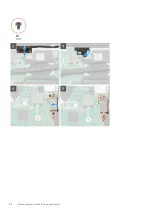
Page 56: ...e latch and disconnect the display cable from the system board 10 Remove the two screws M2x5 that secure the USB Type C port bracket to the system board 11 Remove the six screws M2x4 that secure the system board to the palm rest and keyboard assembly 12 Gently release the ports on the system board from the slots on the palm rest and keyboard assembly and lift the system board off the palm rest and...

Page 57: ...Removing and installing components 57 ...

Page 58: ...58 Removing and installing components ...

Page 59: ...ce the Mylar on the keyboard connector 8 Connect the keyboard backlight cable to the system board and close the latch to secure the cable 9 Connect the touchpad cable to the system board and close the latch to secure the cable 10 Connect the speaker cable to the system board 11 Connect the power adapter cable to the system board 12 Connect the I O board cable to the system board and close the latc...

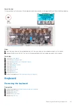
Page 60: ...he system board NOTE The system board can be removed along with the heat sink About this task The figure indicates the location of the keyboard bracket and provides a visual representation of the removal procedure Steps 1 Remove the 39 screws M1 2x2 that secure the keyboard bracket to the keyboard and palm rest assembly 2 Lift the keyboard bracket off the keyboard and palm rest assembly Installing...

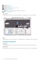
Page 61: ...nstall the system board 2 Install the power adapter port 3 Install the power button with fingerprint reader 4 Install the I O board 5 Install the display assembly 6 Install the CPU fan 7 Install the GPU fan 8 Install the WLAN card 9 Install the battery 10 Install the base cover 11 Follow the procedure in After working inside your computer Keyboard Removing the keyboard Prerequisites 1 Follow the p...

Page 62: ...ation of the keyboard and provides a visual representation of the removal procedure Steps After performing the steps in the pre requisites lift the keyboard along with the cables off the palm rest assembly Installing the keyboard Prerequisites If you are replacing a component remove the existing component before performing the installation procedure About this task The figure indicates the locatio...

Page 63: ...y 7 Install the CPU fan 8 Install the GPU fan 9 Install the WLAN card 10 Install the battery 11 Install the base cover 12 Follow the procedure in After working inside your computer Palm rest Removing the palm rest Prerequisites 1 Follow the procedure in Before working inside your computer 2 Remove the base cover 3 Remove the battery 4 Remove the WLAN card 5 Remove the GPU fan 6 Remove the CPU fan ...

Page 64: ...e indicates the location of the palm rest and provides a visual representation of the removal procedure Steps After performing the steps in the pre requisites we are left with the palm rest Installing the palm rest and keyboard assembly Prerequisites If you are replacing a component remove the existing component before performing the installation procedure About this task The figure indicates the ...

Page 65: ...the power adapter port 6 Install the power button with fingerprint reader 7 Install the I O board 8 Install the display assembly 9 Install the speakers 10 Install the CPU fan 11 Install the GPU fan 12 Install the WLAN card 13 Install the battery 14 Install the base cover 15 Follow the procedure in After working inside your computer Removing and installing components 65 ...

Page 66: ...l com support Intel Trusted Execution Engine Interface In the Device Manager check if the Intel Trusted Execution Engine Interface driver is installed Install the driver update from www dell com support Intel Virtual Button driver In the Device Manager check if the Intel Virtual Button driver is installed Install the driver updates from www dell com support Wireless and Bluetooth drivers In the De...

Page 67: ...ring POST when the DELL logo is displayed watch for the F2 prompt to appear and then press F2 immediately NOTE The F2 prompt indicates that the keyboard is initialized This prompt can appear very quickly so you must watch for it and then press F2 If you press F2 before the F2 prompt this keystroke is lost If you wait too long and the operating system logo appears continue to wait until you see the...

Page 68: ...p options System Information menu General System Information BIOS version Displays the BIOS version number Service Tag Displays the Service Tag of the computer Asset Tag Displays the Asset Tag of the computer Ownership Tag Displays the ownership tag of the computer Manufacture Date Displays the manufacture date of the computer Ownership Date Displays the ownership date of the computer Express Serv...

Page 69: ...n of the computer Panel Type Displays the Panel Type of the computer Native Resolution Displays the native resolution of the computer Audio Controller Displays the audio controller information of the computer Wi Fi Device Displays the wireless device information of the computer Cellular Device Displays the Cellular device information of the computer Bluetooth Device Displays the Bluetooth device i...

Page 70: ...s only effect when the backlight is enabled Default 10 seconds Keyboard Backlight Timeout on Battery Configures the timeout value for the keyboard when the computer is running on battery The keyboard backlight timeout value is only effect when the backlight is enabled Default 10 seconds Fingerprint Reader Enable or disable the fingerprint reader device Miscellaneous Devices Enables or disables var...

Page 71: ...m setup options Secure Boot menu Secure Boot Secure Boot Enable Enables or disables the computer to boot using only validated boot software Default OFF NOTE For Secure Boot to be enabled the computer needs to be in UEFI boot mode and the Enable Legacy Option ROMs option needs to be turned off Secure Boot Mode Selects the Secure Boot operation mode Default Deployed Mode NOTE Deployed Mode should be...

Page 72: ...ter to automatically power on for defined days and times Default Disabled The system will not automatically power up USB Wake Support Enables the USB devices to wake the computer from Standby mode Default OFF Block Sleep Blocks the computer from entering Sleep S3 mode in the operating system Default OFF NOTE If enabled the computer will not go to sleep Intel Rapid Start will be disabled automatica...

Page 73: ...ings or errors are detected NOTE Errors deemed critical to the operation of the computer hardware will always halt the computer Table 11 System setup options Virtualization Support menu Virtualization Intel Virtualization Technology Enables the computer to run a virtual machine monitor VMM Default ON VT for Direct I O Enables the computer to perform Virtualization Technology for Direct I O VT d VT...

Page 74: ...in BIOS block and cannot work if the Boot Block is damaged In addition this feature cannot work in the event of EC corruption ME corruption or a hardware issue The recovery image must exist on an unencrypted partition on the drive Table 14 System setup options System Logs menu System Logs BIOS Events Displays BIOS events Default Keep Thermal Events Displays Thermal events Default Keep Power Events...

Page 75: ...ve up to 32 characters The password can contain the numbers 0 through 9 Only lower case letters are valid upper case letters are not allowed Only the following special characters are allowed space 3 Type the system password that you entered earlier in the Confirm new password field and click OK 4 Press Esc and a message prompts you to save the changes 5 Press Y to save the changes The computer reb...

Page 76: ...rt as described at www dell com contactdell NOTE For information on how to reset Windows or application passwords refer to the documentation accompanying Windows or your application Updating the BIOS Updating the BIOS in Windows environment About this task Follow these steps to update the BIOS Steps 1 Turn on your computer 2 Go to www dell com support 3 Click Product support In the Search support ...

Page 77: ...or you can also update the BIOS from the F12 One Time boot menu on the computer Most of the Dell computers built after 2012 have this capability and you can confirm by booting your computer to the F12 One Time Boot Menu to see if BIOS FLASH UPDATE is listed as a boot option for your computer If the option is listed then the BIOS supports this BIOS update option NOTE Only computers with BIOS Flash ...

Page 78: ... the file and double click the flash target file and then click Submit 6 Click Update BIOS The computer restarts to flash the BIOS 7 The computer will restart after the BIOS update is completed 78 System setup ...

Page 79: ...o not apply pressure to the surface of the battery Do not bend the battery Do not use tools of any type to pry on or against the battery If a battery gets stuck in a device as a result of swelling do not try to free it as puncturing bending or crushing a battery can be dangerous Do not attempt to reassemble a damaged or swollen battery into a laptop Swollen batteries that are covered under warrant...

Page 80: ...light blinks amber along with beep codes indicating failures For example the power and battery status light blinks amber two times followed by a pause and then blinks white three times followed by a pause This 2 3 pattern continues until the computer is turned off indicating no memory or RAM is detected The following table shows different power and battery status light patterns and associated prob...

Page 81: ...lf Test BIST Dell laptops have a built in diagnostic tool that helps you determine if the screen abnormality you are experiencing is an inherent problem with the LCD screen of the Dell laptop or with the video card GPU and PC settings When you notice screen abnormalities like flickering distortion clarity issues fuzzy or blurry image horizontal or vertical lines color fade etc it is always a good ...

Page 82: ...lick Enable to enable the Intel Optane memory 4 On the warning screen select a compatible fast drive and then click Yes to continue enabling Intel Optane memory 5 Click Intel Optane memory Reboot to complete enabling your Intel Optane memory NOTE Applications may take up to three subsequent launches after enablement to see the full performance benefits Disabling Intel Optane memory About this task...

Page 83: ...ea power 5 Replace the battery 6 Replace the base cover 7 Turn on your computer Wi Fi power cycle About this task If your computer is unable to access the Internet due to Wi Fi connectivity issues a Wi Fi power cycle procedure may be performed The following procedure provides the instructions on how to conduct a Wi Fi power cycle NOTE Some ISPs Internet Service Providers provide a modem router com...

Page 84: ...ervice Tag or Express Service Code at www dell com support For more information on how to find the Service Tag for your computer see Locate the Service Tag on your computer Dell knowledge base articles for a variety of computer concerns 1 Go to www dell com support 2 On the menu bar at the top of the Support page select Support Knowledge Base 3 In the Search field on the Knowledge Base page type t...

Reviews: