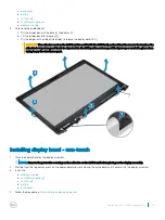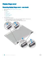
4
Place the computer on the edge of a plane surface with the display facing down.
5
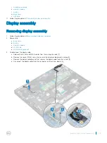
To remove the display assembly:
a Remove the 4 (M2*5) screws that secure the display assembly to the system [1].
b Lift the display assembly away from the system [2].
Installing display assembly
1
Place the chassis on the edge of a plane surface.
2
Align the display assembly to align with the screw holders on the system.
3
Replace the 4 (M2*5) screws to secure the display assembly to the system.
4
Lift the computer and close the display.
5
Connect the display cable to the connector on the system board.
6
Place the metal bracket to secure the display cable.
7
Replace the single M2*5 screw to secure the metal bracket to the system.
8
Route the WLAN and WWAN cables through the routing channels.
9
Install the:
a
b
c
d
e
10 Follow the procedure in
After working inside your computer
.
Display bezel
Removing display bezel - non-touch
1
Follow the procedure in
Before working inside your computer
.
2
Remove the:
36
Removing and installing components
Summary of Contents for Latitude 5290
Page 1: ...Latitude 5290 Owner s Manual Regulatory Model P27S Regulatory Type P27S002 ...
Page 23: ...Removing and installing components 23 ...
Page 85: ...Video driver Verify if the video driver is already installed in the system Software 85 ...
Page 88: ...Image device driver Verify if the image device driver is installed in the system 88 Software ...

