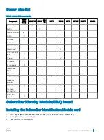
Screw size list
Table 1. Latitude 5290 screw size list
Component
M2*3
(Thin
head)
M2.5*6.3 M2*6 M2
*5
M3*3
M2*2
M2*5
M2*2.5
M2.5*3
M2x5.4
Base cover
8
Battery
1
Heatsink assembly
6
WLAN
1
SSD card
1
Keyboard
5
Display assembly
4
Display panel
2
Power connector
port
1
Palmrest
2
3
2
LED board
1
System board
3
Display hinge
cover
2
Display hinge
6
Hard drive bracket
4
Hard drive
assembly
4
Chassis frame
2
2
3
Touchpad
panel(button)
2
Smart card
module
2
Subscriber Identity Module(SIM) board
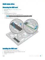
Installing the Subscriber Identification Module card
1
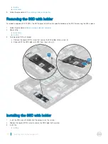
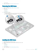
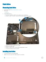
Insert a paperclip or a Subscriber Identification Module (SIM) card removal tool into the pinhole [1].
2
Pull the SIM card tray to remove it [2].
3
Place the SIM on the SIM card tray.
Removing and installing components
7
Summary of Contents for Latitude 5290
Page 1: ...Latitude 5290 Owner s Manual Regulatory Model P27S Regulatory Type P27S002 ...
Page 23: ...Removing and installing components 23 ...
Page 85: ...Video driver Verify if the video driver is already installed in the system Software 85 ...
Page 88: ...Image device driver Verify if the image device driver is installed in the system 88 Software ...


