


Power adapter port
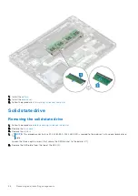
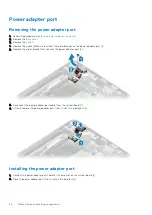
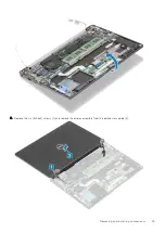
Removing the power adapter port
before working inside your computer
.
2. Remove the
.
3. Remove the
.
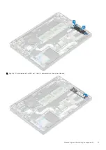
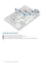
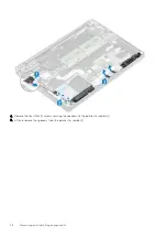
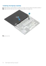
1. Remove the single (M2x3) screw from the metal bracket on the power adapter port [1].
2. Remove the metal bracket that secures the power adapter port [2].
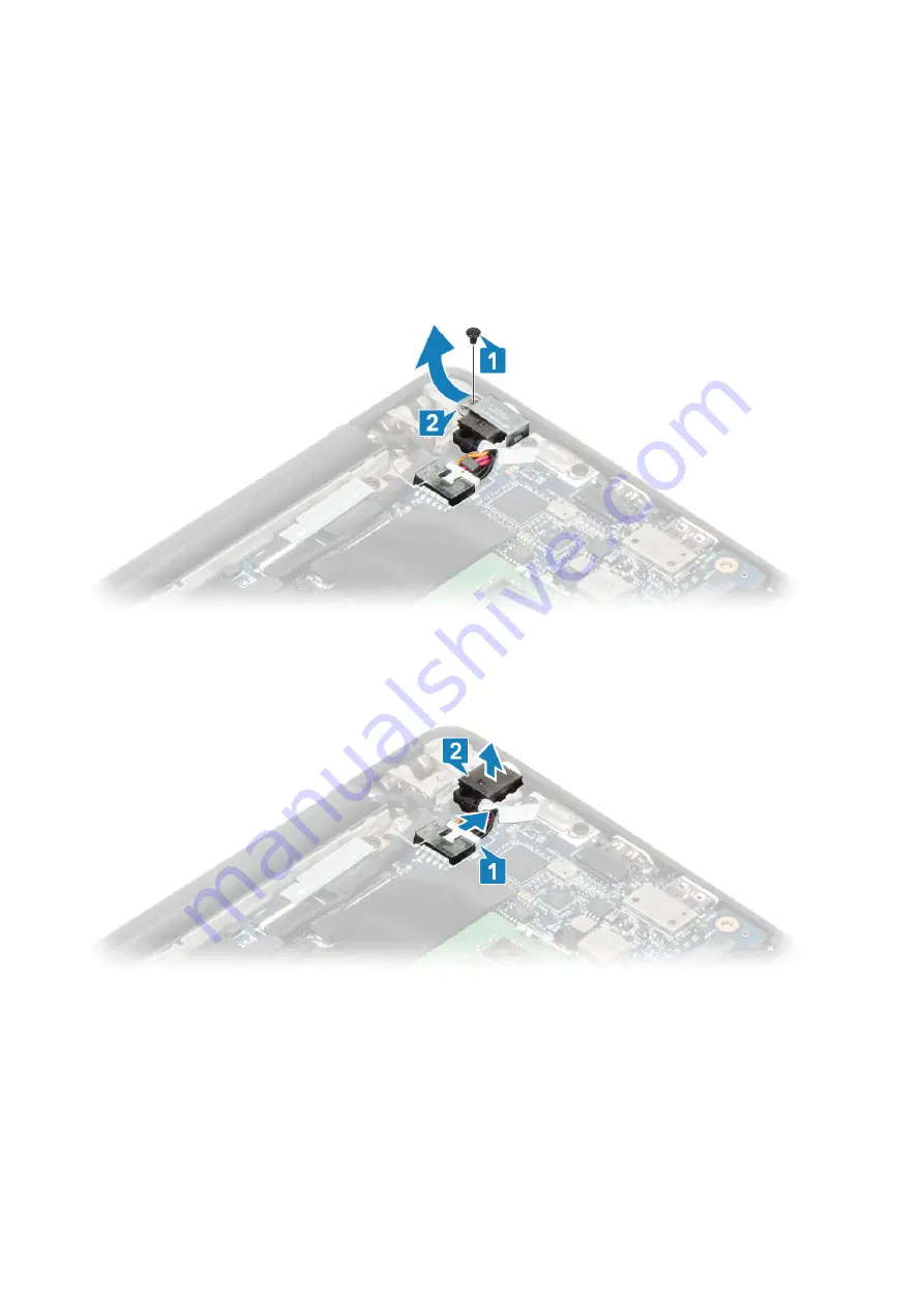
3. Disconnect the power adapter port cable from the system board [1].
4. Lift and remove the power adapter port from its slot in the palmrest [2].
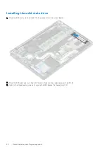
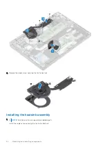
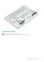
Installing the power adapter port
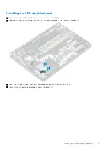
1. Connect the power adapter port cable to its connector on the system board [1].
2. Place the power adapter port into its slot on the palmrest [2].
36
Removing and installing components
Summary of Contents for Latitude 7300
Page 19: ...4 Lift and remove the base cover from the computer Removing and installing components 19 ...
Page 56: ...3 Route the antennae and display cable along the hinges 56 Removing and installing components ...
Page 80: ...Figure 5 Power button board without FPR 80 Removing and installing components ...


