background image

Results

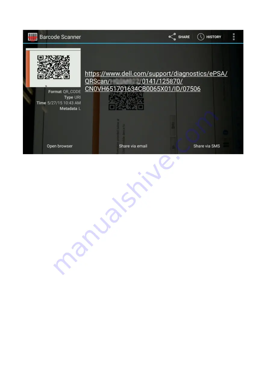
The link generated will take the customer to the Dell Support website which contains information on:

Confirmation of the error code and result outcome

Suggested Part Replacement

If customer is still covered under Dell Warranty

Case reference number if there is an open case under the service tag

Troubleshooting

55

Summary of Contents for Latitude 7310

Page 1: ...Latitude 7310 Service Manual 1 0 0 0 Regulatory Model P33S and P34S Regulatory Type P33S001 and P34S001 August 2020 Rev A01 ...

Page 2: ...ential damage to hardware or loss of data and tells you how to avoid the problem WARNING A WARNING indicates a potential for property damage personal injury or death 2020 Dell Inc or its subsidiaries All rights reserved Dell EMC and other trademarks are trademarks of Dell Inc or its subsidiaries Other trademarks may be trademarks of their respective owners ...

Page 3: ...2 WLAN antennae bracket 24 Removing the WLAN antenna bracket 24 Installing the WLAN antenna bracket 25 Palmrest antenna Optional 26 Removing the Palmrest antenna optional 26 Installing the Palmrest antenna optional 27 Heatsink assembly 28 Removing the heatsink assembly 28 Installing the heatsink assembly 29 Display assembly 31 Removing the display assembly 31 Installing the display assembly 32 Spe...

Page 4: ...g the operating system 49 Dell SupportAssist Pre boot System Performance Check diagnostics 49 Running the SupportAssist Pre Boot System Performance Check 49 Validation Tools 50 System diagnostic lights 56 Flashing BIOS USB key 57 Flashing the BIOS 58 Backup media and recovery options 58 WiFi power cycle 58 LCD Built in Self Test BIST 58 BIOS recovery 59 BIOS recovery using hard drive 59 BIOS recov...

Page 5: ...tions that is shipped with the product or at www dell com regulatory_compliance CAUTION Before touching anything inside your computer ground yourself by touching an unpainted metal surface such as the metal at the back of the computer While you work periodically touch an unpainted metal surface to dissipate static electricity which could harm internal components CAUTION When you disconnect a cable...

Page 6: ...D damage Handle all static sensitive components in a static safe area If possible use anti static floor pads and workbench pads When unpacking a static sensitive component from its shipping carton do not remove the component from the anti static packing material until you are ready to install the component Before unwrapping the anti static packaging ensure that you discharge static electricity fro...

Page 7: ...aterial should be used in the original box that the new part arrived in ESD sensitive devices should be removed from packaging only at an ESD protected work surface and parts should never be placed on top of the ESD bag because only the inside of the bag is shielded Always place parts in your hand on the ESD mat in the system or inside an anti static bag Transporting Sensitive Components When tran...

Page 8: ...he screws are not left attached to such surface when replacing a component NOTE Screw color may vary with the configuration ordered Table 1 Screw list Component Secured to Screw type Quantity Screw image 1 SSD thermal plate 2 SSD 3 eDP bracket 4 Keyboard 1 System board 2 System board 3 System board 4 Keyboard support bracket M2x2 1 1 2 1 3 1 4 2 1 WLAN antenna bracket 2 Fan cage 3 Heatsink assembl...

Page 9: ...2 USB Type C bracket System board M2x5 3 Keyboard 1 Carbon Fiber 2 Aluminum Palmrest assembly M1 6x2 _ 1 17 2 21 Base cover Removing the base cover Prerequisites 1 Follow the procedure in Before working inside your computer About this task The following images indicate the location of the base cover and provide a visual representation of the removal procedure Removing and installing components 9 ...

Page 10: ...10 Removing and installing components ...

Page 11: ...Removing and installing components 11 ...

Page 12: ...Do not slide the scribe through the edge of the top side of the base cover as it damages the latches inside the base cover 4 Use the pull tab and disconnect the battery from the system board Installing the base cover Prerequisites If you are replacing a component remove the existing component before performing the installation procedure About this task The following images indicate the location of...

Page 13: ...Removing and installing components 13 ...

Page 14: ...peratures or disassemble battery packs and cells Do not apply pressure to the surface of the battery Do not bend the battery Do not use tools of any kind to pry on or against the battery Ensure any screws during the servicing of this product are not lost or misplaced to prevent accidental puncture or damage to the battery and other system components If the battery gets stuck inside your computer a...

Page 15: ... Lift and remove the battery from the system unit Installing the battery Prerequisites If you are replacing a component remove the existing component before performing the installation procedure About this task The following images indicate the location of the battery and provide a visual representation of the installation procedure Removing and installing components 15 ...

Page 16: ...oard Next steps 1 Install the a Base cover 2 Follow the procedure in After working inside your computer Solid state drive Removing the solid state drive Prerequisites 1 Follow the procedure in Before working inside your computer 2 Remove the a Base cover 3 Disconnect the battery cable About this task The following images indicate the location of the solid state drive and provide a visual represent...

Page 17: ...Figure 1 2230 SSD Removing and installing components 17 ...

Page 18: ...ystem board 3 Slide the SSD out from the M 2 slot on the system board Installing the solid state drive Prerequisites If you are replacing a component remove the existing component before performing the installation procedure About this task The following images indicate the location of the solid state drive and provide a visual representation of the installation procedure 18 Removing and installin...

Page 19: ...Figure 3 2230 SSD Removing and installing components 19 ...

Page 20: ...ard 2 Push the SSD to align the screw holes on the system board and replace the single M2x2 screw securing it to the system board 3 NOTE Slide the SSD plate into place over the SSD so that the tabs on the SSD plate fit into the openings on the system board shielding cover Replace the SSD thermal plate on top of the SSD and secure it using the single M2x2 screw to the system board 20 Removing and i...

Page 21: ...re connected Next steps If you are replacing a component remove the existing component before performing the installation procedure 1 Connect the battery cable 2 Install the a Base cover 3 RTC reset cycle 4 Follow the procedure in After working inside your computer WWAN card Removing the WWAN card Prerequisites 1 Follow the procedure in Before working inside your computer 2 Remove the a Base cover...

Page 22: ...he WWAN card 4 Lift and remove the WWAN card from its slot on the I O board Installing the WWAN card Prerequisites If you are replacing a component remove the existing component before performing the installation procedure About this task The following images indicate the location of the base cover and provide a visual representation of the installation procedure 22 Removing and installing compone...

Page 23: ...pped with WWAN antennas the WWAN antenna connections on the WWAN card are numbered and color coded Connect the antennas to the correct pins on the WWAN card in accordance with the label on the WWAN card shielding cover Table 2 WWAN antenna cable connection guide Cable Pin Number Antenna Cable 5 Gray White Main 6 Black Gray Auxiliary Removing and installing components 23 ...

Page 24: ... component remove the existing component before performing the installation procedure 1 Connect the battery cable 2 Install the a Base cover 3 RTC reset cycle 4 Follow the procedure in After working inside your computer WLAN antennae bracket Removing the WLAN antenna bracket Prerequisites 1 Follow the procedure in Before working inside your computer 2 Remove the a Base cover 3 Disconnect the batte...

Page 25: ...na cable from WLAN module on the system board Installing the WLAN antenna bracket Prerequisites If you are replacing a component remove the existing component before performing the installation procedure About this task The following images indicate the location of the WLAN antenna bracket and provide a visual representation of the installation procedure Removing and installing components 25 ...

Page 26: ...securing the WLAN antenna bracket to the system board Next steps If you are replacing a component remove the existing component before performing the installation procedure 1 Connect the battery cable 2 Install the a Base cover 3 RTC reset cycle 4 Follow the procedure in After working inside your computer Palmrest antenna Optional Removing the Palmrest antenna optional Prerequisites 1 Follow the p...

Page 27: ...e palmrest assembly Installing the Palmrest antenna optional Prerequisites If you are replacing a component remove the existing component before performing the installation procedure About this task The following images indicate the location of the optional Palmrest antenna and provide a visual representation of the installation procedure Removing and installing components 27 ...

Page 28: ...rming the installation procedure 1 Install the a WLAN antenna bracket b Base cover 2 Follow the procedure in After working inside your computer Heatsink assembly Removing the heatsink assembly Prerequisites 1 Follow the procedure in Before working inside your computer 2 Loosen and remove the M2x2 screw on the SSD thermal plate 3 Remove the a Base cover About this task The following images indicate...

Page 29: ... 3 2 1 3 Disconnect the fan connector from the system board 4 Lift and remove the heatsink assembly from the system board Installing the heatsink assembly Prerequisites If you are replacing a component remove the existing component before performing the installation procedure About this task The following images indicate the location of the heatsink assembly and provide a visual representation of ...

Page 30: ...uring the heatsink assembly to the system board 3 Replace the system board shield on top of the heatsink assembly Next steps If you are replacing a component remove the existing component before performing the installation procedure 1 Replace and tighten the M2x2 screw on the SSD thermal plate 2 Install the a Base cover 3 Follow the procedure in After working inside your computer 30 Removing and i...

Page 31: ...hipped with WWAN card remove the WWAN bracket and disconnect the antennae cables Remove the two M2x2 screws that secures the eDP bracket to the system board and remove it from the system board 2 Disconnect the eDP cable touch cable and camera cable from the system board NOTE The display cable and sensor daughter board cable are bundled together with tape Disconnect the sensor daughter board cable ...

Page 32: ...stalling the display assembly Prerequisites If you are replacing a component remove the existing component before performing the installation procedure About this task The following images indicate the location of the display assembly and provide a visual representation of the installation procedure 32 Removing and installing components ...

Page 33: ...or on the system board and replace the two M2x2 screws securing it to the system board Next steps If you are replacing a component remove the existing component before performing the installation procedure 1 Install the a Base cover 2 Follow the procedure in After working inside your computer Speakers Removing the speaker Prerequisites 1 Follow the procedure in Before working inside your computer ...

Page 34: ...te the location of the speaker and provide a visual representation of the installation procedure Steps 1 Connect the speaker cable to its connector on the system board 2 Align and replace the right speaker into its slot in the palmrest assembly and route the speaker cable along the guide path NOTE The speaker cable is secured with an insulation tape on the touchpad buttons Next steps If you are re...

Page 35: ...ask The following images indicate the location of the smart card reader and provide a visual representation of the removal procedure Steps 1 Disconnect the touchpad cable that is routed over the smart card cable from the system board 2 Disconnect the smart card reader cable from the USH board 3 Peel off the smart card reader cable from the palmrest assembly 4 Remove the four M2x2 5 screws and remo...

Page 36: ...ard reader into its slot on the palmrest assembly 2 Adhere the smart card cable routing it on the palmrest assembly 3 Connect the smart card reader cable to the USH board 4 Route the touchpad cable from over the smart card reader cable and connect it to the system board Next steps 1 Install the a Speakers b Battery c Base cover 2 Replace and tighten the single M2x2 screw on the SSD thermal shield ...

Page 37: ...ation of the I O board and provide a visual representation of the removal procedure NOTE For configurations shipped without a WWAN card a WWAN shield cover and WWAN bracket will be pre installed to the system Follow the steps in the WWAN Card section to remove the shield cover and WWAN bracket Steps 1 Remove the single M2x2 5 screw and remove the finger print reader bracket from over the power but...

Page 38: ...system unit Installing the I O board Prerequisites If you are replacing a component remove the existing component before performing the installation procedure About this task The following images indicate the location of the I O board and provide a visual representation of the installation procedure Steps 1 Align the screw hole with that on the palmrest assembly and replace the I O daughterboard i...

Page 39: ...ing inside your computer Power button with fingerprint reader Removing the power button with fingerprint reader Prerequisites 1 Follow the procedure in Before working inside your computer 2 Remove the a Base cover b Battery c WWAN d SSD thermal shield e WLAN antennae bracket f I O board About this task The following images indicate the location of the power button with fingerprint reader and provi...

Page 40: ...ut this task The following images indicate the location of the power button with fingerprint reader and provide a visual representation of the installation procedure Steps 1 Replace the power button with fingerprint reader into its slot in the palmrest assembly 2 Replace the two M2x2 5 screws securing power button with fingerprint reader to the palmrest assembly Next steps 1 Install the a I O boar...

Page 41: ...assembly NOTE System board can be disassembled without having to remove the heatsink assembly About this task The following images indicate the location of the system board and provide a visual representation of the removal procedure Steps 1 Remove the four M2x3 5 screws securing the F beam FPC and remove it from the I O board 2 Un thread the wireless antennae cables Removing and installing compon...

Page 42: ...crews securing the Type C USB bracket to the system board 6 Remove the USB Type C bracket from the system board 7 Remove the single M2x2 5 screw securing the system board to the palmrest assembly 8 Remove the system board from the system Installing the system board Prerequisites If you are replacing a component remove the existing component before performing the installation procedure About this t...

Page 43: ...ews securing the F beam FPC to the I O board Next steps If you are replacing a component remove the existing component before performing the installation procedure 1 Install the a Heatsink assembly b WLAN antennae bracket c Solid state drive d Battery e Base cover 2 Follow the procedure in After working inside your computer Keyboard Removing the keyboard Prerequisites 1 Follow the procedure in Bef...

Page 44: ...44 Removing and installing components ...

Page 45: ...two M2x2 screws securing the keyboard to the keyboard plate NOTE Screws are located below Colon Semi colon key and between Capslock A and Shift keys Installing the keyboard Prerequisites If you are replacing a component remove the existing component before performing the installation procedure About this task The following images indicate the location of the keyboard and provide a visual represent...

Page 46: ... the palmrest assembly Depending on the configuration the number of screws vary Aluminum palmrest 21 Carbon Fiber palmrest 17 Next steps If you are replacing a component remove the existing component before performing the installation procedure 1 Install the a System board b I O board c Heatsink assembly d WLAN antennae bracket e Battery f Base cover 2 Follow the procedure in After working inside ...

Page 47: ...aving to remove the heatsink assembly n Keyboard About this task The following images indicate the location of the palmrest assembly and provide a visual representation of the removal procedure Steps Once all the underlying components are removed you are left with the palmrest assembly Installing the palmrest assembly Prerequisites If you are replacing a component remove the existing component bef...

Page 48: ...orming the installation procedure 1 Install the a Keyboard b System board c Power button with finger print reader d I O board e Smart card reader f Speakers g Display assembly h Heatsink assembly i Palmrest antenna optional j WLAN antenna bracket k WWAN card l Solid state drive m Battery n Base cover 2 Follow the procedure in After working inside your computer 48 Removing and installing components...

Page 49: ...ell SupportAssist Pre boot System Performance Check diagnostics is embedded with the BIOS and is launched by the BIOS internally The embedded system diagnostics provides a set of options for particular devices or device groups allowing you to Run tests automatically or in an interactive mode Repeat tests Display or save test results Run thorough tests to introduce additional test options to provid...

Page 50: ...te the SupportAssist ePSA ePSA or PSA error codes Error code verification can be done using below two methods Online Enhanced Preboot System Assessment Validation Tool QR scanning using QR APP on Smart Phone Online SupportAssist On board Diagnostics ePSA or PSA Error Codes Validation Tool Usage Guide Steps 1 User to obtain information from SupportAssist error windows 2 Navigate to https www dell c...

Page 51: ...r code use only the last 3 or 4 digits of the code user can enter 0142 or 142 instead of 2000 0142 4 Click on Submit once all the necessary information is entered Results Valid Error Code Example Troubleshooting 51 ...

Page 52: ... above screen which contains information on Confirmation of the error code and result outcome Suggested Part Replacement If customer is still covered under Dell Warranty Case reference number if there is an open case under the service tag Invalid Error Code Example 52 Troubleshooting ...

Page 53: ...an also validate the error code by scanning the QR code with a QR APP on a smartphone Steps 1 User to obtain the QR code from SupportAssist On board Diagnostics error screen 2 User can use any QR code scanner application through the smartphone to scan the QR code Troubleshooting 53 ...

Page 54: ...3 The QR code scanner application will scan the code and automatically generate a link Click the link to proceed 54 Troubleshooting ...

Page 55: ...l Support website which contains information on Confirmation of the error code and result outcome Suggested Part Replacement If customer is still covered under Dell Warranty Case reference number if there is an open case under the service tag Troubleshooting 55 ...

Page 56: ... battery status light blinks amber along with beep codes indicating failures For example the power and battery status light blinks amber two times followed by a pause and then blinks white three times followed by a pause This 2 3 pattern continues until the computer is turned off indicating no memory or RAM is detected The following table shows different power and battery status light patterns and...

Page 57: ...less Main battery and adapter plug in 3 2 PCI video card chip failure Replace the system board 3 3 Recovery image not found Flash latest BIOS version If problem persists replace the system board 3 4 Recovery image found but invalid Flash latest BIOS version If problem persists replace the system board 3 5 Power rail failure Replace the system board 3 6 System BIOS Flash incomplete Replace the syst...

Page 58: ...and fix problems that may occur with Windows Dell proposes multiple options for recovering Windows operating system on your Dell PC For more information see Dell Windows Backup Media and Recovery Options WiFi power cycle About this task If your computer is unable to access the Internet due to WiFi connectivity issues a WiFi power cycle procedure may be performed The following procedure provides th...

Page 59: ... hard drive A02 is the running BIOS The BIOS adds A04 maintains A02 and deletes A00 Having two BIOS version enables the Rollback BIOS feature If the recovery file cannot be stored hard drive is out of space the BIOS sets a flag to indicate this condition The flag is reset in the event it later becomes possible to store the recovery file The BIOS notifies the user during POST and in BIOS Setup the ...

Page 60: ...stem down 8 Holding the Ctrl and Esc keys press the power button to start the system up Keep holding the Ctrl and Esc keys until the BIOS Recovery Menu page is displayed Ensure that the Recover BIOS radio button is selected and click Continue to start the BIOS recovery BIOS recovery using USB drive About this task NOTE Ensure that you have the file type extensions visible in the operating system N...

Page 61: ... this task Flea power is the residual static electricity that remains on the computer even after it has been powered off and the battery has been disconnected from the system board The following procedure provides the instructions on how to release the flea power Steps 1 Turn off your computer 2 Remove the base cover NOTE The battery must be disconnected from the system board see Step 2 in Removin...

Page 62: ...https www dell com support home app knowledgebase 2 Type the subject or keyword in the Search box 3 Click Search to retrieve the related articles Learn and get more information about your product Product specifications Operating system Setting up and using your product Data backup Troubleshooting and diagnostics Factory and system restore BIOS information Dell provides several online and telephone...

Page 63: ...er of the page 3 For customized support a Enter your system Service Tag in the Enter your Service Tag field b Click submit The support page that lists the various support categories is displayed 4 For general support a Select your product category b Select your product segment c Select your product The support page that lists the various support categories is displayed 5 For contact details of Del...

Reviews: