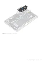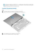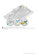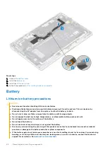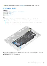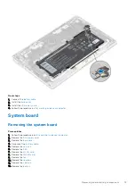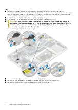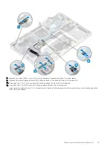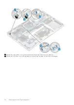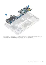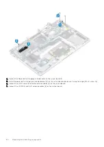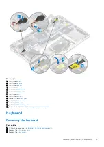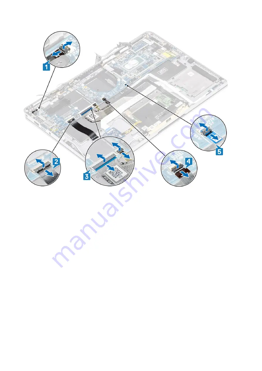
8. Remove the single (M2x2) screw [1] securing the power fingerprint bracket to system board.
9. Remove the power fingerprint bracket [2] and disconnect the cable from the system board [3].
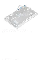
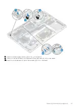
10. Disconnect the LTE P-sensor and isolator antenna cables [4] from the system board.
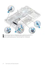
11. Disconnect the LTE MAIN and AUX antennae cables [5] from the system board.
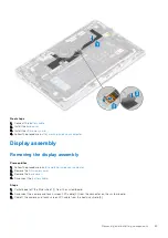
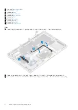
Insert a plastic scribe into the slit at the bottom-left corner of the connector and then carefully pry up the cable connector
from the system board.
Removing and installing components
75
Summary of Contents for Latitude 7400 2-in-1
Page 24: ...4 Pry along the left right and bottom edges of the base 24 Removing and installing components ...
Page 43: ...5 Place the metal shield on the WWAN card Removing and installing components 43 ...
Page 51: ...8 Adhere the Mylar sheet on the system board Removing and installing components 51 ...
Page 56: ...4 Remove the metal foil from the heatsink shield 56 Removing and installing components ...
Page 57: ...5 Remove the heatsink shield from the system board Removing and installing components 57 ...
Page 60: ...3 Place the heatsink shield on the heatsink 60 Removing and installing components ...
Page 61: ...4 Adhere the metal foils on the heatsink shield Removing and installing components 61 ...
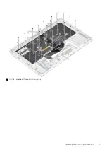
Page 87: ...8 Lift the keyboard off the palmrest assembly Removing and installing components 87 ...

