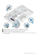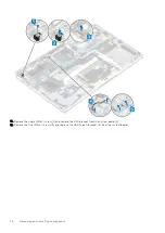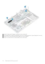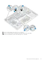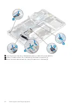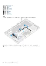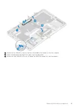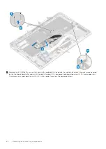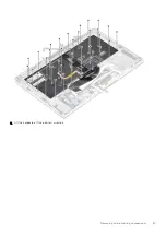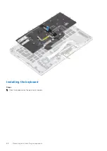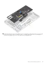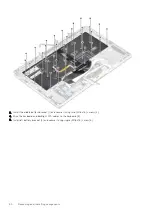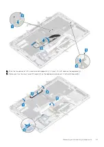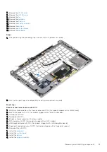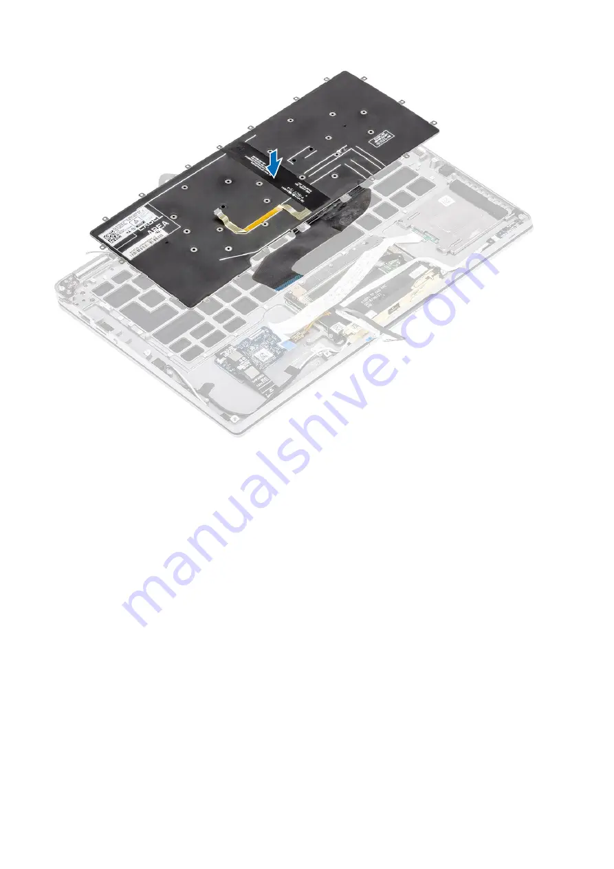
2. Replace the 40 (M1.6x1.5) screws on the keyboard to secure it to the palmrest assembly. Several of the screws are covered
by the touchpad flexible flat cable, LED flexible flat cable (FFC), keyboard flexible printed circuit (FPC), and copper foil.
Technicians must peel back these FFC/FPC/foil in order to access the keyboard screws.
Removing and installing components
89
Summary of Contents for Latitude 7400 2-in-1
Page 24: ...4 Pry along the left right and bottom edges of the base 24 Removing and installing components ...
Page 43: ...5 Place the metal shield on the WWAN card Removing and installing components 43 ...
Page 51: ...8 Adhere the Mylar sheet on the system board Removing and installing components 51 ...
Page 56: ...4 Remove the metal foil from the heatsink shield 56 Removing and installing components ...
Page 57: ...5 Remove the heatsink shield from the system board Removing and installing components 57 ...
Page 60: ...3 Place the heatsink shield on the heatsink 60 Removing and installing components ...
Page 61: ...4 Adhere the metal foils on the heatsink shield Removing and installing components 61 ...
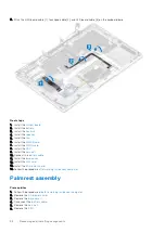
Page 87: ...8 Lift the keyboard off the palmrest assembly Removing and installing components 87 ...

