background image

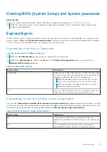
Clearing BIOS (System Setup) and System passwords

About this task

To clear the system or BIOS passwords, contact Dell technical support as described at 

www.dell.com/contactdell

.

NOTE:

 For information on how to reset Windows or application passwords, refer to the documentation accompanying

Windows or your application.

ExpressSign-in

On Dell Latitude systems, the proximity sensor is accessed when the system is ON or in the sleep mode. The valid state of the
proximity sensor is 

Near

, and 

Enable with external monitor

. The proximity feature is automatically disabled while the laptop is

in the On state, and the remaining battery of the laptop is less than 30 minutes.

ExpressSign-in behavior in Near state

The following table explains the 

Near

 state behavior:

NOTE:

 The 

Dell ExpressSign-in

 user interface is the proximity sensor feature.

NOTE:

 In the 

ExpressSign-in

 window, click 

Go

 next to the 

Setup facial recognition

 field to start and setup the

Windows Hello facial sign-in

 option.

Table 24. Near state behavior 

System state

Description

ON/Standby

Wakes up the system when the user is within the sensor Field
of View (FoV) of the system during the ON state and the LED
illuminates solid white light or in the standby state.

NOTE:

 Sensor does not wake the system from the low

power states which is battery life less than 30 minutes.

NOTE:

 Sensor does not support wake the system from

hibernation and power off state.

Off

Does not wake the system from any of the power states even
when the user is within the sensor Field of View (FoV).

ExpressSign-in with the external monitor usage state

You can select 

ExpressSign-in enabled while connected to external monitor(s)

 to 

Yes

 to keep the ExpressSign-in function

still working even when the external monitor is connected. Select 

No

 to temporarily disable the ExpressSign-in functionality with

the external monitor connected. The following table explains the 

External monitor usage state behavior

:

Table 25. External monitor usage state behavior 

System state

Description

Yes

If the system is connected to an external monitor, the
proximity sensor checks whether the user is within the sensor
FoV.

No

This is the default state and the system state remains
unchanged even when the user is outside of sensor FoV.

System setup

111

Summary of Contents for Latitude 7400 2-in-1

Page 1: ...Dell Latitude 7400 2 in 1 Service Manual Regulatory Model P110G Regulatory Type P110G001 August 2021 Rev A03 ...

Page 2: ...tial damage to hardware or loss of data and tells you how to avoid the problem WARNING A WARNING indicates a potential for property damage personal injury or death 2019 2021 Dell Inc or its subsidiaries All rights reserved Dell EMC and other trademarks are trademarks of Dell Inc or its subsidiaries Other trademarks may be trademarks of their respective owners ...

Page 3: ...g the SD memory card 18 Installing the SD memory card 19 SIM card tray 20 Removing the SIM card tray 20 Installing the SIM card tray 21 Base cover 22 Removing the base cover 22 Installing the base cover 26 Battery cable 30 Disconnecting the battery cable 30 Connecting the battery cable 31 Coin cell 32 Removing the coin cell battery 32 Installing the coin cell battery 33 Solid state drive 34 Removi...

Page 4: ...er 5 System setup 95 BIOS overview 95 Entering BIOS setup program 95 Boot menu 95 Navigation keys 96 One time boot menu 96 Boot Sequence 96 System setup options 97 General options 97 System configuration 98 Video screen options 100 Security 100 Secure boot 102 Intel Software Guard Extensions options 103 Performance 103 Power management 104 Post behavior 105 Manageability 106 Virtualization support...

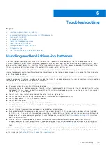
Page 5: ...ced Pre Boot System Assessment ePSA diagnostics 116 Running the ePSA diagnostics 116 Built in self test BIST 116 M BIST 116 LCD Power rail test L BIST 117 LCD Built in Self Test BIST 117 System diagnostic lights 118 Recovering the operating system 118 Real Time Clock RTC Reset 119 Backup media and recovery options 119 WiFi power cycle 119 Drain residual flea power perform hard reset 119 Chapter 7 ...

Page 6: ... the online or telephone service and support team Damage due to servicing that is not authorized by Dell is not covered by your warranty Read and follow the safety instructions that came with the product CAUTION To avoid electrostatic discharge ground yourself by using a wrist grounding strap or by periodically touching an unpainted metal surface at the same time as touching a connector on the bac...

Page 7: ... the cable from the network device 5 Disconnect your computer and all attached devices from their electrical outlets 6 Press and hold the power button while the computer is unplugged to ground the system board NOTE To avoid electrostatic discharge ground yourself by using a wrist grounding strap or by periodically touching an unpainted metal surface at the same time as touching a connector on the ...

Page 8: ...e answer to the consumers demands with a theoretically 10 times faster than its predecessor In a nutshell USB 3 1 Gen 1 features are as follows Higher transfer rates up to 5 Gbps Increased maximum bus power and increased device current draw to better accommodate power hungry devices New power management features Full duplex data transfers and support for new transfer types Backward USB 2 0 compati...

Page 9: ...maximum resolution latency and video compression perspective it s easy to imagine that with 5 10 times the bandwidth available USB video solutions should work that much better Single link DVI requires almost 2Gbps throughput Where 480Mbps was limiting 5Gbps is more than promising With its promised 4 8Gbps speed the standard will find its way into some products that previously weren t USB territory...

Page 10: ...se portable battery packs you charge your smartphones and other portable devices from today You could plug your laptop into an external display connected to a power cable and that external display would charge your laptop as you used it as an external display all via the one little USB Type C connection To use this the device and the cable have to support USB Power Delivery Just having a USB Type ...

Page 11: ...interface HDMI provides an interface between any compatible digital audio video source such as a DVD player or A V receiver and a compatible digital audio and or video monitor such as a digital TV DTV The primary advantage is cable reduction and content protection provisions HDMI supports standard enhanced or high definition video plus multichannel digital audio on a single cable HDMI 1 4a Feature...

Page 12: ... Gorilla Glass Corning Gorilla Glass 5 Corning s latest composition was formulated to address breakage the 1 consumer complaint according to Corning s research The new glass is just as thin and light as previous versions but has been formulated to deliver dramatically improved native damage resistance allowing improved in field performance Corning Gorilla Glass 5 has been tested for performance wh...

Page 13: ...ptical Refractive Index 590 nm Core glass 1 50 Compression layer 1 51 Photo elastic constant 30 3 nm cm MPa Core index is used for FSM based measurements since it is unaffected by ion exchange conditions Chemical Durability Durability is measured via weight loss per surface area after immersion in the solvents shown below Values are highly dependent upon actual testing conditions Data reported is ...

Page 14: ...66 6 96 0 014 2986 6 96 0 014 Terminated coaxial line similar to that outlined in NIST Technical Notes 1520 and 1355 R Putting Corning Gorilla Glass 5 to the test Greater damage resistance upto 1 8X with deep abrasion Faster chemical strengthening with high Compressive Stress and deeper depth of compression Shallower check depth with higher abrasions levels Enables thickness reduction 14 Technolog...

Page 15: ...Major components of your system 1 Base cover 2 Heatsink shield 3 Major components of your system 15 ...

Page 16: ...3 WWAN shield 14 Solid state drive 15 SSD shield NOTE Dell provides a list of components and their part numbers for the original system configuration purchased These parts are available according to warranty coverages purchased by the customer Contact your Dell sales representative for purchase options 16 Major components of your system ...

Page 17: ...llowing tools Phillips 0 screwdriver Phillips 1 screwdriver Plastic scribe T 30 torx screwdriver NOTE The 0 screw driver is for screws 0 1 and the 1 screw driver is for screws 2 4 Screw List The following table shows the screw list and the images for Dell Latitude 7400 2 in 1 for different components and locations Table 7 Screw Size List Component Screw type Quantity Image Base cover Captive screw...

Page 18: ...M1 6x2 5 4 Display assembly M2 5x3 5 6 Battery M1 6x4 5 M2x3 1 4 System board M2x2 M2x4 M2x3 2 2 5 Keyboard M1 6x1 5 1 2 40 SD memory card Removing the SD memory card Steps 1 Press the SD memory card to eject it from the SD memory card slot 1 2 Remove the SD memory card from the computer 2 18 Removing and installing components ...

Page 19: ...Installing the SD memory card Steps Insert the SD memory card into its slot 1 until it clicks into place 2 Removing and installing components 19 ...

Page 20: ...that are shipped with WWAN card only Steps 1 Insert a paperclip or a SIM card removal tool into the pinhole on the SIM card tray 1 2 Push the pin to disengage the lock and eject the SIM card tray 2 3 Pull the SIM card tray out of the computer 3 20 Removing and installing components ...

Page 21: ...Installing the SIM card tray Steps Install the SIM card tray into its slot on the computer 1 and push to lock it in place 2 Removing and installing components 21 ...

Page 22: ...e cover Prerequisites 1 Follow the procedure in before working inside your computer 2 Remove the SD memory card Steps 1 Loosen the 10 captive screws that secure the base cover to the computer 22 Removing and installing components ...

Page 23: ...as shown in the image 3 Pry the base cover along the edges from the top side 2 to separate the base cover from the computer 2 CAUTION Do not pull on the base cover from the top side immediately after prying it open from the recesses as it can damage the base cover Removing and installing components 23 ...

Page 24: ...4 Pry along the left right and bottom edges of the base 24 Removing and installing components ...

Page 25: ...5 Slide the base cover outwards before removing it off the computer and then life the base cover off the computer Removing and installing components 25 ...

Page 26: ...Installing the base cover Steps 1 Slide in base cover and place it on the computer 26 Removing and installing components ...

Page 27: ...2 Press along the edges of the base cover until it clicks into place Removing and installing components 27 ...

Page 28: ...3 Tighten the 10 captive screws to secure the base cover to the computer 28 Removing and installing components ...

Page 29: ...4 Press the two highlighted middle area of the system as shown in the image after the screws are secured to complete the installation process Removing and installing components 29 ...

Page 30: ...computer Battery cable Disconnecting the battery cable Prerequisites 1 Follow the procedure in before working inside your computer 2 Remove the SD memory card 3 Remove the base cover Steps Disconnect the battery cable from the connector on the system board 30 Removing and installing components ...

Page 31: ...Connecting the battery cable Steps Connect the battery cable to the connector on the system board Removing and installing components 31 ...

Page 32: ...ng the coin cell battery Prerequisites 1 Follow the procedure in before working inside your computer 2 Remove the SD memory card 3 Remove the base cover 4 Disconnect the battery cable Steps 1 Disconnect the coin cell battery cable from the connector on the system board 1 2 Peel and lift the coin cell battery off the computer 2 32 Removing and installing components ...

Page 33: ...Installing the coin cell battery Steps 1 Affix the coin cell battery to the system 1 2 Connect the coin cell battery cable to the connector on the system board 2 Removing and installing components 33 ...

Page 34: ... Solid state drive Removing the solid state drive Prerequisites 1 Follow the procedure in before working inside your computer 2 Remove the SD memory card 3 Remove the base cover 4 Disconnect the battery cable Steps 1 Peel off the metal foil 1 and the black tape 2 that partially covers the solid state drive SSD cover 34 Removing and installing components ...

Page 35: ...2 Remove the single M2x2 screw 1 that secures the SSD shield to the system board 3 Lift to remove the SSD shield from the system board 2 Removing and installing components 35 ...

Page 36: ...the SSD module from the connector on the system board Installing the solid state drive Steps 1 Align and slide the solid state drive SSD module into the connector on the system board 36 Removing and installing components ...

Page 37: ...D shield on the SSD module 1 and replace the single M2x2 screw 2 to secure it to the system board 3 Affix the black tape 1 and the metal foil 2 to secure the SSD shield in place Removing and installing components 37 ...

Page 38: ... the SD memory card 3 Remove the base cover 4 Disconnect the battery cable Steps 1 Partially peel off the Mylar sheet that covers the WLAN card 1 2 Remove the single M2x2 screw 2 that secures the WLAN card bracket to the WLAN card 3 Remove the WLAN card bracket from the WLAN card 4 Disconnect the wireless antennae cables 4 from the connectors on the WLAN card 5 Slide and remove the WLAN card 5 fro...

Page 39: ...WLAN antenna card cables 2 to the connector on the WLAN card 3 Align the screw hole on the WLAN card bracket with the screw hole on the WLAN card 3 4 Replace the single M2x2 4 screw to secure the WLAN card to the system board 5 Stick the Mylar sheet on the system board to cover the WLAN card 5 Removing and installing components 39 ...

Page 40: ...in after working inside your computer WWAN card Removing the WWAN card Prerequisites 1 Follow the procedure in before working inside your computer 2 Remove the SD memory card 3 Remove the base cover 4 Disconnect the battery cable Steps 1 Remove the metal shield from the WWAN card 40 Removing and installing components ...

Page 41: ...ket to the WWAN card 3 Remove the WWAN bracket 2 from the WWAN card 4 Disconnect the wireless antennae cables 3 from the connectors on the WWAN card 5 Slide and remove the WWAN card 4 from the connector on the system board Removing and installing components 41 ...

Page 42: ...or on the system board 2 Connect the WWAN antenna cables 2 to the connector on the WWAN card 3 Align the screw hole on the WWAN card bracket with the screw hole on the WWAN card 3 4 Replace the single M2x2 screw 4 to secure the WWAN card to the system board 42 Removing and installing components ...

Page 43: ...5 Place the metal shield on the WWAN card Removing and installing components 43 ...

Page 44: ...ct the battery cable NOTE For the Latitude 7400 2 in 1 model shipped with a WWAN card there is an L shaped bracket P sensor bracket that covers the four WWAN LTE antenna cable connections to the system board The screw that secures the bracket to the system also helps secure the fan to the system Technicians must first remove the bracket before removing the fan and then reinstall the bracket after ...

Page 45: ...2 Disconnect the fan cable 1 from the connector on the system board 1 3 Partially peel off the metal foil 2 and the black tape 3 on the SSD shield Removing and installing components 45 ...

Page 46: ...sor bracket to the system board 5 Remove the WWAN P sensor bracket 2 from the system board 6 Partially peel off the padded gasket 1 from the fan case 7 Remove the single M2x2 screw 2 that secures the fan to the system board 46 Removing and installing components ...

Page 47: ...g the palmrest on the bottom side of the fan Technicians should not lift the fan directly up as it may damage the fan Partially lift the left side of the fan and slide it to the left to remove it from the computer Removing and installing components 47 ...

Page 48: ...TE antenna cable connections to the system board The screw that secures the bracket to the system also helps secure the fan to the system Technicians must first remove the bracket before removing the fan and then reinstall the bracket after the fan is reinstalled Steps 1 Slide the fan at an angle into its slot on the system board 48 Removing and installing components ...

Page 49: ...2 Replace the single M2x2 screw 1 to secure the fan to the system board 3 Adhere the padded rubber gasket 2 on the fan case Removing and installing components 49 ...

Page 50: ...e on the fan 5 Replace the single M2x2 screw 2 to secure the WWAN P sensor bracket to the fan 6 Connect the fan cable 1 to the connector on the system board 7 Adhere the black tape 2 and the metal foil 3 partially covering the SSD shield 50 Removing and installing components ...

Page 51: ...8 Adhere the Mylar sheet on the system board Removing and installing components 51 ...

Page 52: ...re in before working inside your computer 2 Remove the SD memory card 3 Remove the base cover 4 Disconnect the battery cable Steps 1 Disconnect the speaker cable 1 from the connector from the system board and peel off the speaker flex cable 2 from the battery 2 Remove the three M1 6x1 4 screws 1 that secure the speakers to the system board and lift the speakers off the computer 2 52 Removing and i...

Page 53: ...the speakers Steps 1 Align the screw holes on the speakers 1 with the screw holes on the chassis 2 Replace the three M1 6x1 4 screws 2 that secure the speakers to the chassis Removing and installing components 53 ...

Page 54: ...3 Connect the speaker cable 1 to the connector on the system board and adhere the speaker flex cable 2 on the battery 54 Removing and installing components ...

Page 55: ... the procedure in before working inside your computer 2 Remove the SD memory card 3 Remove the base cover 4 Disconnect the battery cable Steps 1 Partially peel off the Mylar sheet 1 from the system board 2 Disconnect the camera and touch screen FPC cable 2 from the connector on the system board 3 Peel off the camera and touch screen FPC cable from the heatsink shield 3 Removing and installing comp...

Page 56: ...4 Remove the metal foil from the heatsink shield 56 Removing and installing components ...

Page 57: ...5 Remove the heatsink shield from the system board Removing and installing components 57 ...

Page 58: ...6 Remove the four M1 6x2 5 screws 1 that secure the heatsink on the system board 7 Lift the heatsink 2 off the system board 58 Removing and installing components ...

Page 59: ...heatsink Steps 1 Align the screw holes on the heatsink 1 with the screw holes on the system board 2 Replace the four M1 6x2 5 screws 2 that secure the heatsink to the system board Removing and installing components 59 ...

Page 60: ...3 Place the heatsink shield on the heatsink 60 Removing and installing components ...

Page 61: ...4 Adhere the metal foils on the heatsink shield Removing and installing components 61 ...

Page 62: ...d touch screen FPC cables on the heatsink shield 1 6 Connect the camera and touch screen FPC cables 2 to the connector on the system board 7 Adhere the Mylar sheet 3 on the system board 62 Removing and installing components ...

Page 63: ...1 Follow the procedure in before working inside your computer 2 Remove the SD memory card 3 Remove the base cover 4 Disconnect the battery cable Steps 1 Partially peel off the Mylar sheet 1 from the system board 2 Disconnect the camera and touch screen FPC cable 2 from the connector on the system board 3 Peel off the camera and touch screen FPC cable from the heatsink shield 3 Removing and install...

Page 64: ...icians must flip open in order to disconnect the display cable from the system board After flipping open the latch technicians must grasp the left and right sides of the cable s connector head and disconnect the display cable from the system board in a direct upward motion to prevent damage to the connector s pins 6 Disconnect the display cable from the connector on the system board 3 64 Removing ...

Page 65: ...7 Remove the six M2 5x3 5 screws 1 that secures the display hinges to the computer 8 Lift the display assembly off the computer 2 Removing and installing components 65 ...

Page 66: ...need to be replaced replace the entire display assembly Installing the display assembly Steps 1 Install the display assembly with hinges open at 180º aligned to the computer 1 2 Replace the six M2 5x3 5 screws 1 that secures the display hinges to the computer 2 3 Connect the display cable 1 to the connector on the system board 4 Close the latch 2 and adhere the tape on the display cable 3 66 Remov...

Page 67: ... touch screen FPC and adhere it on the heatsink shield 1 6 Connect the camera and touch screen FPC to the connector on the system board 2 and stick the Mylar sheet on the system board 3 Removing and installing components 67 ...

Page 68: ...jects Do not expose the battery to high temperatures or disassemble battery packs and cells Do not apply pressure to the surface of the battery Do not bend the battery Do not use tools of any kind to pry on or against the battery Ensure any screws during the servicing of this product are not lost or misplaced to prevent accidental puncture or damage to the battery and other system components If th...

Page 69: ... plastic bracket at the top left corner and within the routing channels along the left and bottom side of the battery As a result technicians must be careful when unrouting the antenna cables from their routing guides while they are still attached to the wireless card If there is difficulty in unrouting the antenna cables from their routing channels remove the WLAN card from the computer to create...

Page 70: ... extra M2x4 screw shown in green Remove the screw before removing the battery from the computer Table 8 Battery screw description Size Amount 4 cell battery Yellow M2x3L 5 Red M1 6x4 5L 1 6 cell battery Green M2x4L 1 70 Removing and installing components ...

Page 71: ...tery Steps 1 Align the screw holes on the battery with the screw holes on the palmrest assembly 1 2 Replace the four M2x3 screws and single M1 6x4 5 screw that secure the battery to the palmrest assembly 2 Removing and installing components 71 ...

Page 72: ...the battery disassembly section 3 Stick the tape on wireless antennae cable securing it to the battery 1 4 Thread the antennae cables along the routing channels and supporting bracket on the battery 2 5 Connect the battery cable to the system board 72 Removing and installing components ...

Page 73: ... system board Prerequisites 1 Follow the procedure in before working inside your computer 2 Remove the SD memory card 3 Remove the base cover 4 Disconnect the battery cable 5 Remove the coin cell 6 Remove the SSD 7 Remove the WLAN card 8 Remove the WWAN card 9 Remove the fan 10 Remove the speakers 11 Remove the heatsink 12 Remove the battery Removing and installing components 73 ...

Page 74: ...lay cable connector to flip open the latch 4 4 CAUTION The connector for the display cable features an actuator that locks it in place on the system board Flip open the latch to disconnect the display cable from the system board Grasp the left and right sides of the cable s connector head and disconnect the display cable from the system board in a direct upward motion to prevent damage to the conn...

Page 75: ...he system board 3 10 Disconnect the LTE P sensor and isolator antenna cables 4 from the system board 11 Disconnect the LTE MAIN and AUX antennae cables 5 from the system board Insert a plastic scribe into the slit at the bottom left corner of the connector and then carefully pry up the cable connector from the system board Removing and installing components 75 ...

Page 76: ...move the single M2x2 screw 1 and remove the SSD bracket from the system board 2 13 Remove the two M2x4 screws 3 and remove the USB Type C bracket 4 from the system board 76 Removing and installing components ...

Page 77: ...ray must first be removed from the system before removing the system board Remove the five M2x3 screws 1 and remove the system board from the computer 2 NOTE Lifting the system board from the thin middle portion might damage the board Removing and installing components 77 ...

Page 78: ... After removing all brackets and disconnecting all cables there are five screws that secure the system board to the palmrest One of the screw is covered by the Real Time Clock RTC battery Technicians must first peel the RTC battery off the system board in order to access all the screws for the system board 78 Removing and installing components ...

Page 79: ...ype C bracket 1 on the system board and secure it using two M2x4 screws 2 on the system board 3 Install the SSD bracket 3 and secure it using a single M2x2 screw 4 to the system board Removing and installing components 79 ...

Page 80: ...power button finger print reader bracket 2 on the system board and secure it using the single M2x2 screw 3 6 Connect the LTE P sensor and isolator antenna cables 4 on the system board 7 Connect the LTE MAIN and AUX antennae cables 5 on the system board 80 Removing and installing components ...

Page 81: ...utton cable to the system board 1 9 Connect the USH board cable 2 and keyboard with backlight cable 3 to the system board 10 Connect the touchpad cable 4 and LED board cable 5 to the system board Removing and installing components 81 ...

Page 82: ...rd and connect its cable to the system board 2 12 Connect the display cable to the system board 3 and flip close the actuator 4 13 Secure the display cable connector by sticking the tape on the system board 5 82 Removing and installing components ...

Page 83: ...e coin cell 9 Connect the battery cable 10 Install the base cover 11 Install the SIM card 12 Install the SD memory card 13 Follow the procedure after working inside your computer Keyboard Removing the keyboard Prerequisites 1 Follow the procedure in before working inside your computer 2 Remove the SD memory card 3 Remove the base cover Removing and installing components 83 ...

Page 84: ...e the heatsink 13 Remove the system board Steps 1 Peel off the USH board cable 1 touchpad cable 2 and LED board cable 3 from the keyboard base 2 Peel back the two pieces of LTE antenna module copper foil 1 3 and LTE AUX cable from the keyboard 2 3 Disconnect the smartcard reader FPC from the USH board 4 and peel off the FPC cable from the keyboard 5 84 Removing and installing components ...

Page 85: ... the middle battery bracket 2 from the computer 5 Peel off the keyboard and backlight FPC cables from the keyboard 3 6 Remove the single M1 6x1 5 screw 4 to remove the left battery bracket 5 from the computer Removing and installing components 85 ...

Page 86: ...mbly Several of the screws are covered by the touchpad flexible flat cable LED flexible flat cable FFC keyboard flexible printed circuit FPC and copper foil Technicians must peel back these FFC FPC foil in order to access the keyboard screws 86 Removing and installing components ...

Page 87: ...8 Lift the keyboard off the palmrest assembly Removing and installing components 87 ...

Page 88: ...Installing the keyboard Steps 1 Place the keyboard on the palmrest assembly 88 Removing and installing components ...

Page 89: ...sembly Several of the screws are covered by the touchpad flexible flat cable LED flexible flat cable FFC keyboard flexible printed circuit FPC and copper foil Technicians must peel back these FFC FPC foil in order to access the keyboard screws Removing and installing components 89 ...

Page 90: ...bracket 1 and secure it using two M1 6x1 5 screws 2 4 Stick the keyboard and backlight FPC cables to the keyboard 3 5 Install left battery bracket 4 and secure it using single M1 6x1 5 screw 5 90 Removing and installing components ...

Page 91: ...o pieces of LTE antenna module copper foil 1 3 and LTE AUX cable on the keyboard 2 7 Route and stick the smart card FPC cable 4 on the keyboard and connect it to the USH board 5 Removing and installing components 91 ...

Page 92: ... Install the SSD 9 Install the coin cell 10 Connect the battery cable 11 Install the base cover 12 Install the SIM card 13 Install the SD memory card 14 Follow the procedure after working inside your computer Palmrest assembly Prerequisites 1 Follow the procedure in before working inside your computer 2 Remove the SD memory card 3 Remove the base cover 4 Disconnect the battery cable 5 Remove the c...

Page 93: ... antenna module with antenna cables and FPCs for models shipped with a WWAN card 2 SmartCard reader with FFC for models shipped with a SmartCard reader 3 LED board with FFC 4 Touchpad with FPC 5 Wireless antenna module with antenna cables 6 NFC module with FPC for models shipped with an NFC reader 7 USH daughter board with FPC for models shipped with a USH daughter board 8 Fingerprint reader modul...

Page 94: ...AN card 9 Install the WLAN card 10 Install the SSD 11 Install the coin cell 12 Connect the battery cable 13 Install the base cover 14 Install the SIM card 15 Install the SD memory card 16 Follow the procedure after working inside your computer 94 Removing and installing components ...

Page 95: ...d setup password Clearing BIOS System Setup and System passwords ExpressSign in BIOS overview The BIOS manages data flow between the computer s operating system and attached devices such as hard disk video adapter keyboard mouse and printer Entering BIOS setup program Steps 1 Turn on your computer 2 Press F2 immediately to enter the BIOS setup program NOTE If you wait too long and the operating sy...

Page 96: ...nu turn on your computer and then press F12 immediately NOTE It is recommended to shutdown the computer if it is on The one time boot menu displays the devices that you can boot from including the diagnostic option The boot menu options are Removable Drive if available STXXXX Drive if available NOTE XXX denotes the SATA drive number Optical Drive if available SATA Hard Drive if available Diagnosti...

Page 97: ...Displays the battery status and the type of AC adapter connected to the computer Boot Sequence Allows you to change the order in which the computer attempts to find an operating system The options are Windows Boot Manager Boot List Option Allows you to change the boot list options Click one of the following options Legacy External Devices UEFI Default Advanced Boot Options Allows you to Enable Leg...

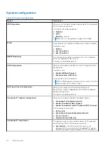
Page 98: ...ons are set by default NOTE USB keyboard and mouse always work in the BIOS setup irrespective of these settings Dell Type C Dock Configuration Allows you to connect to Dell WD and TB family of docks Type C Docks independent of USB and thunderbolt adapter configuration This option is enabled by default Thunderbolt Adapter Configuration Allows you to enable or disable Thunderbolt options Thunderbolt...

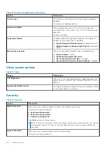
Page 99: ... This option is set by default Keyboard Illumination This field lets you choose the operating mode of the keyboard illumination feature Disabled The Keyboard illumination will always be off or 0 Dim Enable the keyboard illumination feature at 50 brightness Bright Enable the keyboard illumination feature at 100 brightness level Keyboard Backlight Timeout on AC This feature defines the timeout value...

Page 100: ...bled Secure Digital Card SD Read Only Mode Disabled Video screen options Table 11 Video Option Description LCD Brightness Allows you to set the display brightness depending upon the power source On Battery 50 is default and On AC 100 default Dynamic Backlight Control This option Enables or Disables the Dynamic Backlight Control if the Panel supports this feature Security Table 12 Security Option D...

Page 101: ...whether changes to the setup options are allowed when an Administrator Password is set If disabled the setup options are locked by the admin password Allow Wireless Switch Changes This option is not set by default UEFI Capsule Firmware Updates Allows you to update the system BIOS via UEFI capsule update packages Enable UEFI Capsule Firmware Updates This option is set by default TPM 2 0 Security Al...

Page 102: ...o enable or disable additional UEFI SMM Security Mitigation protection SMM Security Mitigation This option is not set by default Secure boot Table 13 Secure Boot Option Description Secure Boot Enable Allows you to enable or disable the Secure Boot Feature Secure Boot Enable Default Secure Boot Mode Changes to the Secure Boot operation mode modifies the behaviour of Secure Boot to allow evaluation ...

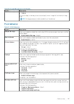
Page 103: ...mance Option Description Multi Core Support This field specifies whether the process has one or all cores enabled The performance of some applications improves with the additional cores All Default 1 2 3 Intel SpeedStep Allows you to enable or disable the Intel SpeedStep mode of processor Enable Intel SpeedStep This option is set by default C States Control Allows you to enable or disable the addi...

Page 104: ... wireless radio will ne enabled Control WLAN radio This option is not set by default Block Sleep This option lets you to block entering to sleep in OS environment This option is not set by default Peak Shift Allows you enable of disable the Peak shift feature This feature when enabled minimizes the AC power usage at times of peak demand Battery doesnot charge between the Peak Shift start and end t...

Page 105: ...r of these keys Fn Lock Default Click one of the following options Lock Mode Disable Standard Lock Mode Enable Secondary Default Fastboot Allows you to speed up the boot process by bypassing some of the compatibility steps Click one of the following options Minimal Default Thorough Auto Extended BIOS POST Time Allows you to create an additional preboot delay Click one of the following options 0 se...

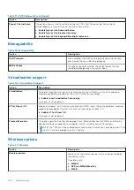
Page 106: ...achine Monitor VMM can utilize the additional hardware capabilities provided by the Intel Virtualization technology Enable Intel Virtualization Technology This option is set by default VT for Direct I O Enables or disables the Virtual Machine Monitor VMM from utilizing the additional hardware capabilities provided by the Intel Virtualization technology for direct I O Enable VT for Direct I O This ...

Page 107: ...is option is set by default Data Wipe Allows you to securely erase data from all internal storage devices Wipe on Next Boot This option is not set by default Bios Recovery BIOS Recovery from Hard Drive This option is set by default Allows you to recover the corrupted BIOS from a recovery file on the HDD or an external USB key BIOS Auto Recovery Allows you to recover the BIOS automatically NOTE BIO...

Page 108: ... screen instructions For more information see knowledge base article 000124211 at www dell com support Updating the BIOS in Linux and Ubuntu To update the system BIOS on a computer that is installed with Linux or Ubuntu see the knowledge base article 000131486 at www dell com support Updating the BIOS using the USB drive in Windows About this task CAUTION If BitLocker is not suspended before updat...

Page 109: ...date your BIOS from the F12 One Time boot menu you need the following USB drive formatted to the FAT32 file system key does not have to be bootable BIOS executable file that you downloaded from the Dell Support website and copied to the root of the USB drive AC power adapter that is connected to the computer Functional computer battery to flash the BIOS Perform the following steps to perform the B...

Page 110: ...he changes as prompted by the pop up message 5 Press Y to save the changes The computer restarts Deleting or changing an existing system setup password Prerequisites Ensure that the Password Status is Unlocked in the System Setup before attempting to delete or change the existing System and or Setup password You cannot delete or change an existing System or Setup password if the Password Status is...

Page 111: ...tion ON Standby Wakes up the system when the user is within the sensor Field of View FoV of the system during the ON state and the LED illuminates solid white light or in the standby state NOTE Sensor does not wake the system from the low power states which is battery life less than 30 minutes NOTE Sensor does not support wake the system from hibernation and power off state Off Does not wake the s...

Page 112: ...rt the Dell Proximity Sensor window when the system is ON or in the sleep mode 2 Click Change PC Behavior based on your proximity to the PC that is displayed at the bottom of the Settings screen 3 You can also double click Systray to start the Dell ExpressSign in window 4 Right click Systray to view the context menu The options in the context menu are Table 26 Context menu options System state Opt...

Page 113: ...conds default 90 seconds and 120 seconds If Away is set to OFF the Lock timer option is grayed out Supported hinge angles The ExpressSign in works as configured in a supported four hinge angles for a particular mode The ExpressSign in does not change the existing state if you are within the sensor FoV for an unsupported hinge angle Once the system is in the supported hinge angle the ExpressSign in...

Page 114: ...Table 28 Supported hinge angles continued System with status Supported hinge angle Illustration Tent Not supported 114 System setup ...

Page 115: ...To discharge the battery unplug the AC adapter from the system and operate the system only on battery power When the system will no longer power on when the power button is pressed the battery is fully discharged Do not crush drop mutilate or penetrate the battery with foreign objects Do not expose the battery to high temperatures or disassemble battery packs and cells Do not apply pressure to the...

Page 116: ...t the bottom left corner Diagnostics front page is displayed 5 Click the arrow in the lower right corner to go to the page listing The items detected are listed 6 To run a diagnostic test on a specific device press Esc and click Yes to stop the diagnostic test 7 Select the device from the left pane and click Run Tests 8 If there are any issues error codes are displayed Note the error code and vali...

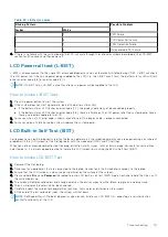
Page 117: ...For cases when a 2 8 error code is shown replace the system board LCD Built in Self Test BIST Dell laptops have a built in diagnostic tool that helps you determine if the screen abnormality you are experiencing is an inherent problem with the LCD screen of the Dell laptop or with the video card GPU and PC settings When you notice screen abnormalities like flickering distortion clarity issues fuzzy...

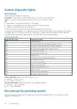
Page 118: ...ght patterns and associated problems Table 30 LED codes Diagnostic light codes Problem description 2 1 Processor failure 2 2 System board BIOS or ROM Read Only Memory failure 2 3 No memory or RAM Random Access Memory detected 2 4 Memory or RAM Random Access Memory failure 2 5 Invalid memory installed 2 6 System board or chipset error 2 7 Display failure 2 8 LCD power rail failure Replace system bo...

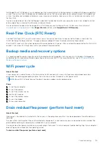
Page 119: ...ia and recovery options It is recommended to create a recovery drive to troubleshoot and fix problems that may occur with Windows Dell proposes multiple options for recovering Windows operating system on your Dell PC For more information see Dell Windows Backup Media and Recovery Options WiFi power cycle About this task If your computer is unable to access the internet due to WiFi connectivity iss...

Page 120: ... Press and hold the power button for 20 seconds to drain the flea power 6 Install the battery 7 Install the base cover 8 Connect the power adapter to your computer 9 Turn on your computer NOTE For more information about performing a hard reset see the knowledge base article 000130881 at www dell com support 120 Troubleshooting ...

Page 121: ...and telephone based support and service options Availability varies by country and product and some services may not be available in your area To contact Dell for sales technical support or customer service issues Steps 1 Go to Dell com support 2 Select your support category 3 Verify your country or region in the Choose a Country Region drop down list at the bottom of the page 4 Select the appropr...

Reviews: