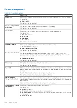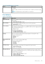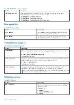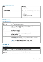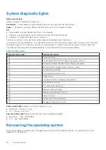
System diagnostic lights
Battery-status light
Indicates the power and battery-charge status.
Solid white
— Power adapter is connected and the battery has more than 5 percent charge.
Amber
— Computer is running on battery and the battery has less than 5 percent charge.
Off
●
Power adapter is connected and the battery is fully charged.
●
Computer is running on battery and the battery has more than 5 percent charge.
●
Computer is in sleep state, hibernation, or turned off.
The power and battery-status light blinks amber along with beep codes indicating failures.
For example, the power and battery-status light blinks amber two times followed by a pause, and then blinks white three times
followed by a pause. This 2,3 pattern continues until the computer is turned off indicating no memory or RAM is detected.
The following table shows different power and battery-status light patterns and associated problems.
Table 30. LED codes
Diagnostic light codes
Problem description
2,1
Processor failure
2,2
System board: BIOS or ROM (Read-Only Memory) failure
2,3
No memory or RAM (Random-Access Memory) detected
2,4
Memory or RAM (Random-Access Memory) failure
2,5
Invalid memory installed
2,6
System-board or chipset error
2,7
Display failure
2,8
LCD power rail failure. Replace system board
3,1
Coin-cell battery failure
3,2
PCI, video card/chip failure
3,3
Recovery image not found
3,4
Recovery image found but invalid
3,5
Power-rail failure
3,6
System BIOS Flash incomplete
3,7
Management Engine (ME) error
Camera status light:
Indicates whether the camera is in use.
●
Solid white — Camera is in use.
●
Off — Camera is not in use.
Caps Lock status light:
Indicates whether Caps Lock is enabled or disabled.
●
Solid white — Caps Lock enabled.
●
Off — Caps Lock disabled.
Recovering the operating system
When your computer is unable to boot to the operating system even after repeated attempts, it automatically starts Dell
SupportAssist OS Recovery.
118
Troubleshooting
Summary of Contents for Latitude 7400 2-in-1
Page 24: ...4 Pry along the left right and bottom edges of the base 24 Removing and installing components ...
Page 43: ...5 Place the metal shield on the WWAN card Removing and installing components 43 ...
Page 51: ...8 Adhere the Mylar sheet on the system board Removing and installing components 51 ...
Page 56: ...4 Remove the metal foil from the heatsink shield 56 Removing and installing components ...
Page 57: ...5 Remove the heatsink shield from the system board Removing and installing components 57 ...
Page 60: ...3 Place the heatsink shield on the heatsink 60 Removing and installing components ...
Page 61: ...4 Adhere the metal foils on the heatsink shield Removing and installing components 61 ...
Page 87: ...8 Lift the keyboard off the palmrest assembly Removing and installing components 87 ...

