Removing and installing components
Recommended tools
The procedures in this document require the following tools:
•
Phillips #0 screwdriver
•
Phillips #1 screwdriver
•
Plastic scribe-Recommended for field technician.
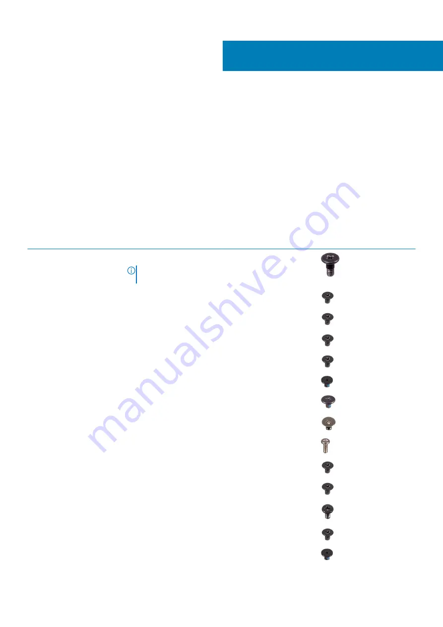
Screw List
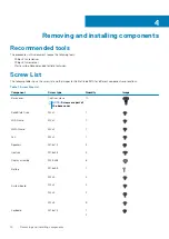
The following table shows the screw list and the images for Dell Latitude 9410, for different components and locations.
Table 7. Screw Size List
Component
Screw type
Quantity
Image
Base cover
Captive screws
NOTE:
Screws are part of
the base cover
10
Solid State Drive
M2x2
1
WLAN card
M2x2
1
WWAN card
M2x2
1
Fan
M2x2
1
Speakers
M1.6x1.4
3
Heatsink
M1.6x2.5
4
Display assembly
M2.5x3.5
6
Battery
M1.6x4.5
1
M2x3
4
System board
M2x2
2
M2x4
2
M2x3
5
Keyboard
M1.6x1.5
1
2
4
14
Removing and installing components
Summary of Contents for Latitude 9410
Page 1: ...Dell Latitude 9410 Service Manual Regulatory Model P110G Regulatory Type P110G001 ...
Page 36: ...5 Place the metal shield on the WWAN card 36 Removing and installing components ...
Page 49: ...4 Remove the metal foil from the heatsink shield Removing and installing components 49 ...
Page 50: ...5 Remove the heatsink shield from the system board 50 Removing and installing components ...
Page 53: ...3 Place the heatsink shield on the heatsink Removing and installing components 53 ...
Page 54: ...4 Adhere the metal foils on the heatsink shield 54 Removing and installing components ...
Page 80: ...8 Lift the keyboard off the palmrest assembly 80 Removing and installing components ...


