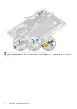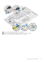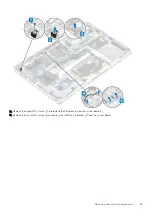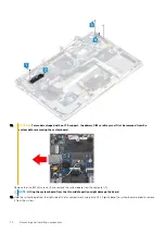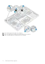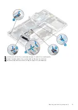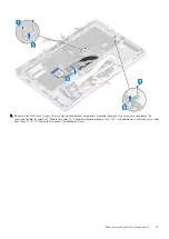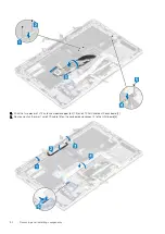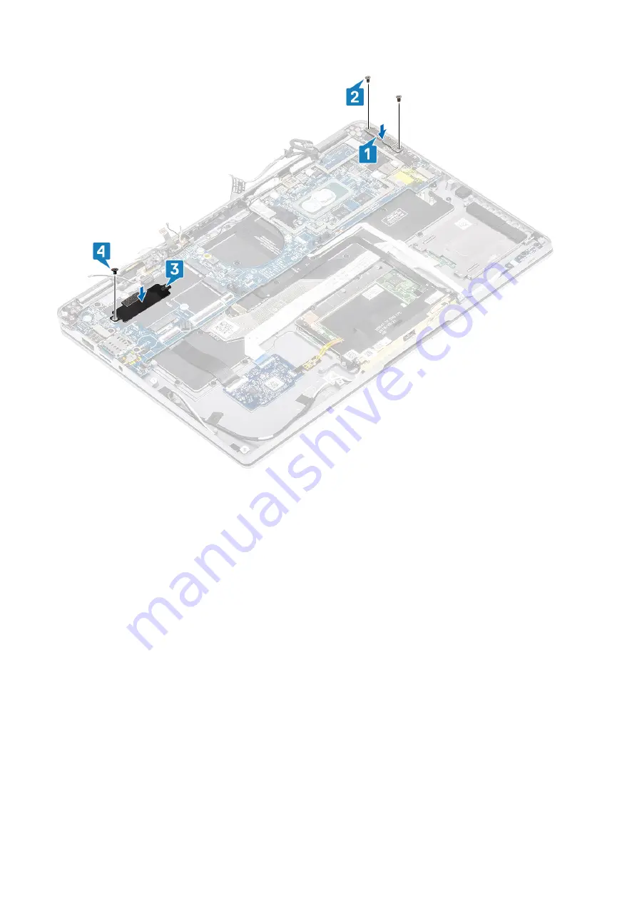
4. Connect the Power button/fingerprint reader cable to the system board [1].
5. Install the power button/finger print reader bracket [2] on the system board and secure it using the single (M2x2) screw [3].
6. Connect the LTE P-sensor and isolator antenna cables [4] on the system board.
7. Connect the LTE MAIN and AUX antennae cables [5] on the system board.
Removing and installing components
73
Summary of Contents for Latitude 9410
Page 1: ...Dell Latitude 9410 Service Manual Regulatory Model P110G Regulatory Type P110G001 ...
Page 36: ...5 Place the metal shield on the WWAN card 36 Removing and installing components ...
Page 49: ...4 Remove the metal foil from the heatsink shield Removing and installing components 49 ...
Page 50: ...5 Remove the heatsink shield from the system board 50 Removing and installing components ...
Page 53: ...3 Place the heatsink shield on the heatsink Removing and installing components 53 ...
Page 54: ...4 Adhere the metal foils on the heatsink shield 54 Removing and installing components ...
Page 80: ...8 Lift the keyboard off the palmrest assembly 80 Removing and installing components ...

