Removing and Replacing Parts
31
2
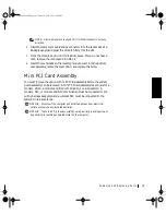
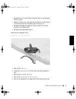
Remove the four 4-mm screws located across the top of the bezel.
3
Use a scribe at the indentations to pry out the two plastic screw covers
located at the bottom of the bezel.
4
Remove the two 4-mm screws located at the bottom of the bezel.
5
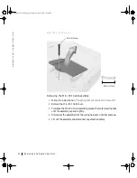
Separate the bezel from the display-assembly top cover.
The bezel is secured to the display assembly top cover with plastic tabs
around the sides. Use a plastic scribe to help separate the bezel from
the top cover.
Removing the Display Panel
1
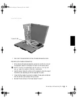
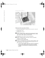
Remove the
2
Detach the
from the strain relief and the graphics
card.
3
4
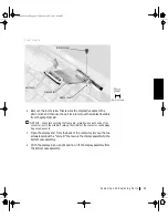
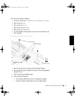
Remove the 4-mm screw securing the plastic flex cable mounting
bracket to the top cover assembly.
5
Remove the six 3-mm screws (three on each side) from the right and
left sides of the panel.
6
Lift the display panel and flex cable out of the top cover assembly.
7
Disconnect the flex cable from the two connectors (a ZIF and a
standard connector) on the display panel assembly.
64mcwc11.book Page 31 Tuesday, April 3, 2001 9:58 AM


