38
Remo ving and Replacing Parts
w
w
w
.d
e
ll.c
o
m
|
s
u
p
p
o
rt
.d
e
ll.
c
o
m
NOTICE:
Hold the microprocessor down while turning the cam lock screw to
prevent intermittent contact between the cam lock screw and microprocessor
(see “
2
Tighten the cam lock screw.
NOTICE:
Do not over- or undertighten the screw. Tighten it until the screw
indicator points to the “closed” or “locked” indicator on the socket.
3
Replace the microprocessor thermal cooling assembly.
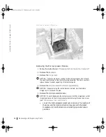
C l o s i ng th e Mi c ro p r o ce s s o r Re t ai n in g Cl i p
4
While pressing lightly down on the center of the retaining clip, insert a
flat-blade screwdriver into the latch mechanism and pivot the top of
the screwdriver away from the clip to close the latch.
Video Graphics Board
NOTICE:
Disconnect the computer and attached devices from electrical
outlets and remove any installed batteries.
64mcwc11.book Page 38 Tuesday, April 3, 2001 9:58 AM


