AC Adapter
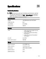
NOTE: 65 W AC
adapter is
available only for
computers with
integrated video
card.
Input voltage
100 VAC to 240 VAC
100 VAC to 240 VAC
Input current
(maximum)
1.50 A/1.60 A/1.70 A/
2.10 A
1.50 A/1.60 A/1.70 A
Input frequency 50 Hz to 60 Hz
50 Hz to 60 Hz
Output power
65 W, 90 W, and 150
W
90 W
Output current
3.34 A, 4.62 A and 7.70
A (continuous)
4.62 A (continuous)
Rated output
voltage
19.5 +/– 1.0 VDC
19.5 +/– 1.0 VDC
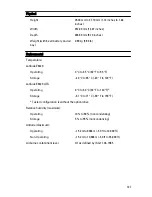
Temperature
range:
Operating
0 °C to 40 °C (32 °F to
104 °F)
0 °C to 40 °C (32 °F to 104 °F)
Non-
Operating
–40 °C to 70 °C (–40 °F
to 158 °F)
–40 °C to 70 °C (–40 °F to 158 °F)
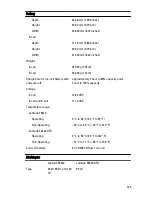
Physical
Latitude E6420
Height
26.90 mm to 32.40 mm (1.06 inches to 1.27
inches)
Width
352.00 mm (13.86 inches)
Depth
241.00 mm (9.49 inches)
Weight (with 4-cell battery)
2.07 kg (4.56 lb)
Latitude E6420 ATG
126
Summary of Contents for Latitude E6420
Page 8: ...8 ...
Page 20: ...20 ...
Page 26: ...26 ...
Page 38: ...9 Slide and remove the WLAN card out from its slot on the system board 38 ...
Page 40: ...40 ...
Page 42: ...9 Slide the WWAN card from its connector and remove it from the computer 42 ...
Page 44: ...44 ...
Page 50: ...50 ...
Page 52: ...10 Disconnect the bluetooth cable 52 ...
Page 54: ...54 ...
Page 59: ...9 Remove the tape securing the keyboard cable from the keyboard 10 Unlock the cable holder 59 ...
Page 64: ...64 ...
Page 70: ...13 Remove the Smart Card Reader from the computer 70 ...
Page 72: ...72 ...
Page 74: ...16 Remove the media board from the computer 74 ...
Page 76: ...76 ...
Page 80: ...22 Remove the screws from the video cable holder 23 Remove the video cable holder 80 ...
Page 83: ...29 Slide to unlock system board from the port connectors 30 Remove the system board 83 ...
Page 86: ...23 Unthread the speaker cable 24 Remove the speaker from the system 86 ...
Page 88: ...88 ...
Page 90: ...24 Unthread the video and wireless antenna cables 25 Unthread the modem cable 90 ...
Page 92: ...29 Remove the whole modem cable assembly by pulling it out from the base 92 ...
Page 94: ...94 ...
Page 96: ...22 Remove the I O board from the computer 96 ...
Page 98: ...98 ...
Page 100: ...23 Remove the DC in bracket 24 Remove the DC in cable from the system 100 ...
Page 101: ...25 Push in the DC in trim and remove it from the system 101 ...
Page 105: ...105 ...
Page 109: ...109 ...
Page 116: ...116 ...
Page 118: ...118 ...
Page 128: ...128 ...
Page 144: ...144 ...

