Option
Description
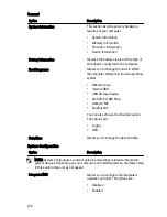
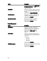
NOTE: This feature is only functional
when the AC power adapter is
connected. If the AC power adapter is
removed during Standby, the system
setup will remove power from all of the
USB ports to conserve battery power.
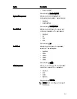
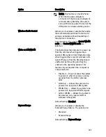
Wireless Radio Control
Allows you to enable or disable the feature
that automatically switches from wired or
wireless networks without depending on
the physical connection.
Default Setting: The options Control WLAN
radio and Control WWAN radio are
selected.
Wake on LAN/WLAN
This field allows the computer to power up
from the off state when triggered by a
special LAN signal or from Hibernate state
when triggered by a special wireless LAN
signal. Wake-up from the Standby state is
unaffected by this setting and must be
enabled in the operating system. This
feature only works when the computer is
connected to AC.
•
Disabled — Does not allow the system
to power on when it receives a wake-
up signal from the LAN or wireless
LAN.
•
LAN Only — Allows the system to be
powered on by special LAN signals.
•
WLAN Only — Allows the system to be
powered on by special WLAN signals.
•
LAN or WLAN — Allows the system to
be powered on by special LAN or
wireless LAN signals.
Default Setting: Disabled
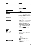
ExpressCharge
Allows you to enable or disable the
ExpressCharge feature. The options are:
•
Standard
•
ExpressCharge
Default Setting: ExpressCharge
137
Summary of Contents for Latitude E6420
Page 8: ...8 ...
Page 20: ...20 ...
Page 26: ...26 ...
Page 38: ...9 Slide and remove the WLAN card out from its slot on the system board 38 ...
Page 40: ...40 ...
Page 42: ...9 Slide the WWAN card from its connector and remove it from the computer 42 ...
Page 44: ...44 ...
Page 50: ...50 ...
Page 52: ...10 Disconnect the bluetooth cable 52 ...
Page 54: ...54 ...
Page 59: ...9 Remove the tape securing the keyboard cable from the keyboard 10 Unlock the cable holder 59 ...
Page 64: ...64 ...
Page 70: ...13 Remove the Smart Card Reader from the computer 70 ...
Page 72: ...72 ...
Page 74: ...16 Remove the media board from the computer 74 ...
Page 76: ...76 ...
Page 80: ...22 Remove the screws from the video cable holder 23 Remove the video cable holder 80 ...
Page 83: ...29 Slide to unlock system board from the port connectors 30 Remove the system board 83 ...
Page 86: ...23 Unthread the speaker cable 24 Remove the speaker from the system 86 ...
Page 88: ...88 ...
Page 90: ...24 Unthread the video and wireless antenna cables 25 Unthread the modem cable 90 ...
Page 92: ...29 Remove the whole modem cable assembly by pulling it out from the base 92 ...
Page 94: ...94 ...
Page 96: ...22 Remove the I O board from the computer 96 ...
Page 98: ...98 ...
Page 100: ...23 Remove the DC in bracket 24 Remove the DC in cable from the system 100 ...
Page 101: ...25 Push in the DC in trim and remove it from the system 101 ...
Page 105: ...105 ...
Page 109: ...109 ...
Page 116: ...116 ...
Page 118: ...118 ...
Page 128: ...128 ...
Page 144: ...144 ...


