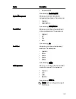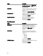
POST Behavior
Option
Description
Adapter Warnings
Allows you to enable or disable the system
setup (BIOS) warning messages when you
use certain power adapters.
Default Setting: Enable Adapter Warnings
is selected.
Keypad (Embedded)
Allows you to choose one or two methods
to enable the keypad that is embedded in
the internal keyboard.
•
Fn Key Only
•
By Num Lk
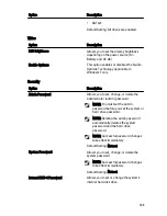
Default Setting: Fn Key Only
Mouse/Touchpad
Allows you to define how the system
handles mouse and touchpad input. The
options are:
•
Serial Mouse
•
PS2 Mouse
•
Touchpad/PS-2 Mouse
Default Setting: Touchpad/PS-2 Mouse
Numlock Enable
Allows you to enable the Numlock option
when the computer boots.
Default Setting: Enable Numlock is
selected.
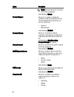
Fn Key Emulation
Allows you to set the option where the
<Scroll Lock> key is used to simulate the
<Fn> key feature.
Default Setting: Enable Fn Key Emulation is
selected.
POST HotKeys
Allows you enable the sign-on screen
message display indicating the keystroke
sequence to access the System Setup
option menu.
Default Setting: Enable F12 Boot Option
Menu is selected.
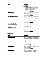
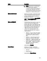
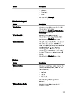
Fastboot
Allows to set the option to speed up the
boot process. The options are:
138
Summary of Contents for Latitude E6420
Page 8: ...8 ...
Page 20: ...20 ...
Page 26: ...26 ...
Page 38: ...9 Slide and remove the WLAN card out from its slot on the system board 38 ...
Page 40: ...40 ...
Page 42: ...9 Slide the WWAN card from its connector and remove it from the computer 42 ...
Page 44: ...44 ...
Page 50: ...50 ...
Page 52: ...10 Disconnect the bluetooth cable 52 ...
Page 54: ...54 ...
Page 59: ...9 Remove the tape securing the keyboard cable from the keyboard 10 Unlock the cable holder 59 ...
Page 64: ...64 ...
Page 70: ...13 Remove the Smart Card Reader from the computer 70 ...
Page 72: ...72 ...
Page 74: ...16 Remove the media board from the computer 74 ...
Page 76: ...76 ...
Page 80: ...22 Remove the screws from the video cable holder 23 Remove the video cable holder 80 ...
Page 83: ...29 Slide to unlock system board from the port connectors 30 Remove the system board 83 ...
Page 86: ...23 Unthread the speaker cable 24 Remove the speaker from the system 86 ...
Page 88: ...88 ...
Page 90: ...24 Unthread the video and wireless antenna cables 25 Unthread the modem cable 90 ...
Page 92: ...29 Remove the whole modem cable assembly by pulling it out from the base 92 ...
Page 94: ...94 ...
Page 96: ...22 Remove the I O board from the computer 96 ...
Page 98: ...98 ...
Page 100: ...23 Remove the DC in bracket 24 Remove the DC in cable from the system 100 ...
Page 101: ...25 Push in the DC in trim and remove it from the system 101 ...
Page 105: ...105 ...
Page 109: ...109 ...
Page 116: ...116 ...
Page 118: ...118 ...
Page 128: ...128 ...
Page 144: ...144 ...

