Installing the Speakers
1. Place the speaker back into the system.
2. Route the speaker cable.
3. Tighten the screws securing the speaker assembly.
4. Install the
System Board
.
5. Install the
ExpressCard Cage
.
6. Install the
Palmrest Assembly
.
7. Install the
Modem Card
.
8. Install the
Keyboard
.
9. Install the
Keyboard Trim
.
10. Install the
Bluetooth Card
.
11. Install the
Heat Sink and Processor
.
12. Install the
Coin Cell Battery
.
13. Install the
WWAN Card
.
14. Install the
WLAN Card
.
15. Install the
Hard Drive
.
16. Install the
Memory
.
17. Install the
Optical Drive
.
18. Install the
ExpressCard
.
19. Install the
Base Cover
.
20. Install the
SD Card
.
21. Install the
Battery
.
22. Install the
ATG Port Cover
(only for E6420 ATG systems).
23. Install the
ATG Handle
(only for E6420 ATG systems).
24. Follow the procedures in
After Working Inside Your Computer
.
87
Summary of Contents for Latitude E6420
Page 8: ...8 ...
Page 20: ...20 ...
Page 26: ...26 ...
Page 38: ...9 Slide and remove the WLAN card out from its slot on the system board 38 ...
Page 40: ...40 ...
Page 42: ...9 Slide the WWAN card from its connector and remove it from the computer 42 ...
Page 44: ...44 ...
Page 50: ...50 ...
Page 52: ...10 Disconnect the bluetooth cable 52 ...
Page 54: ...54 ...
Page 59: ...9 Remove the tape securing the keyboard cable from the keyboard 10 Unlock the cable holder 59 ...
Page 64: ...64 ...
Page 70: ...13 Remove the Smart Card Reader from the computer 70 ...
Page 72: ...72 ...
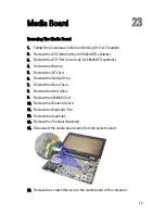
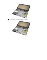
Page 74: ...16 Remove the media board from the computer 74 ...
Page 76: ...76 ...
Page 80: ...22 Remove the screws from the video cable holder 23 Remove the video cable holder 80 ...
Page 83: ...29 Slide to unlock system board from the port connectors 30 Remove the system board 83 ...
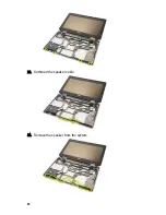
Page 86: ...23 Unthread the speaker cable 24 Remove the speaker from the system 86 ...
Page 88: ...88 ...
Page 90: ...24 Unthread the video and wireless antenna cables 25 Unthread the modem cable 90 ...
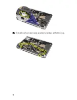
Page 92: ...29 Remove the whole modem cable assembly by pulling it out from the base 92 ...
Page 94: ...94 ...
Page 96: ...22 Remove the I O board from the computer 96 ...
Page 98: ...98 ...
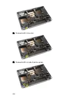
Page 100: ...23 Remove the DC in bracket 24 Remove the DC in cable from the system 100 ...
Page 101: ...25 Push in the DC in trim and remove it from the system 101 ...
Page 105: ...105 ...
Page 109: ...109 ...
Page 116: ...116 ...
Page 118: ...118 ...
Page 128: ...128 ...
Page 144: ...144 ...

