background image

Guia de Noções Básicas

135

e

Selecione o modo de emulação de terminal para 

VT100

.

f

Selecione Terminal keys (Teclas do terminal) para as teclas de função, 
de seta e Ctrl. Certifique-se de que a configuração corresponde à 
opção Terminal keys (Teclas de terminal) e não a Windows keys 
(Teclas Windows).

3

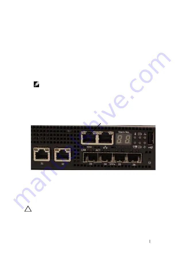
Conecte o conector RJ-45 do cabo diretamente à porta de console do 
comutador. A porta de console do Dell Networking está localizada no lado 
direito do painel frontal e está identificada com um símbolo 

|O|O|

, como 

mostrado na Figura 1-8.


NOTA: 

o acesso de console serial ao gerenciador de pilha está disponível 

a partir de qualquer porta serial por meio da CLI local. Apenas uma sessão de 

console serial é suportada de cada vez.

Figura 1-8. Localização da porta de console do N3132PX-ON

A porta RJ-45 à direita da porta de console destina-se ao gerenciamento 
Ethernet fora da banda.

Como conectar um comutador N3132PX-ON 

a uma fonte de energia


AVISO: 

leia as informações de segurança no manual de 

Informações de 

segurança e de normalização

 manual assim como as informações de segurança 

de outros comutadores que se conectam ou dão suporte ao comutador. 

Porta de console

Summary of Contents for N2128PX-ON

Page 1: ...ll Networking N2128PX ON N3132PX ON Switches Getting Started Guide Guide de mise en route Guia de Noções Básicas Guía de introducción Regulatory Model N2128PX ON N3132PX ON Regulatory Type E05W003 E06W003 ...

Page 2: ......

Page 3: ...Dell Networking N2128PX ON N3132PX ON Switches Getting Started Guide Regulatory Models N2128PX ON N3132PX ON ...

Page 4: ...potential for property damage personal injury or death ____________________ Copyright 2016 Dell Inc All rights reserved This product is protected by U S and international copyright and intellectual property laws Dell and the Dell logo are trademarks of Dell Inc in the United States and or other jurisdictions All other marks and names mentioned herein may be trademarks of their respective companies...

Page 5: ...ation 9 Rack Mounting an N2128PX ON Switch 9 Installing in a Rack 9 Installing as a Free standing Switch 10 Stacking Multiple N2128PX ON Switches 10 3 Starting and Configuring the N2128PX ON Switch 11 Connecting an N2128PX ON Switch to a Terminal 12 Connecting an N2128PX ON Switch to a Power Source 13 AC and DC Power Connection 13 Booting the N2128PX ON Switch 14 ...

Page 6: ...tilation System 26 N3132PX ON Model Summary 27 5 N3132PX ON Installation 28 Rack Mounting a N3132PX ON Switch 28 Rack Mounting Safety Considerations 28 Installing the Dell ReadyRail System 29 Installing as a Free standing Switch 33 Stacking Multiple N3132PX ON Switches 33 6 Starting and Configuring the N3132PX ON Switch 34 Connecting an N3132PX ON Switch to a Terminal 35 Connecting an N3132PX ON S...

Page 7: ...rming the N3132PX ON Initial Configuration 38 Enabling Remote Management 38 Initial Configuration Procedure 39 Example Session 40 Dell Easy Setup Wizard Console Example 41 Next Steps 45 7 NOM Information Mexico Only 47 ...

Page 8: ...6 Contents ...

Page 9: ...of the network is recommended to verify network configuration and operation with the new DNOS version N2128PX ON Hardware Overview This section contains information about device characteristics and modular hardware configurations for the Dell Networking N2128PX ON switch Power Consumption for N2128PX ON PoE Switches Table 1 1 describes the power consumption for N2128PX ON PoE switches The system p...

Page 10: ...ximum Steady Power W N2128PX ON 100V 60Hz MPS 9 92A 986 5W 110V 60Hz MPS 8 93A 975 7W 120V 60Hz MPS 8 01A 955 4W 220V 50Hz MPS 4 44A 945 4W 240V 50Hz MPS 4 08A 951 4W Model Input Voltage Power Supply Configuration Maximum Steady Current Consumption A Maximum Steady Power W N2128PX ON 100V 60Hz Main PSU MPS 11 83A 1175W 110V 60Hz Main PSU MPS 10 71A 1169W 120V 60Hz Main PSU MPS 9 84A 1168 9W 220V 5...

Page 11: ...k or attach it to a wall CAUTION Disconnect all cables from the switch before continuing Remove all self adhesive pads from the underside of the switch if they have been attached CAUTION When mounting multiple switches into a rack mount the switches from the bottom up 1 Place the supplied rack mounting bracket on one side of the switch ensuring that the mounting holes on the switch line up to the ...

Page 12: ...n a rack Install the switch on a flat surface if you are not installing it in a rack The surface must be able to support the weight of the switch and the switch cables The switch is supplied with four self adhesive rubber pads 1 Attach the self adhesive rubber pads on each location marked on the bottom of the switch 2 Set the switch on a flat surface and make sure that it has proper ventilation by...

Page 13: ...and Configuring the N2128PX ON Switch The following flow chart provides an overview of the steps you use to perform the initial configuration after the switch is unpacked and mounted Figure 1 2 Installation and Configuration Flow Chart ...

Page 14: ...mputer with a serial port running VT100 terminal emulation software such as HyperTerminal A serial cable provided with an RJ 45 connector for the console port and DB 9 connector for the terminal Perform the following tasks to connect a terminal to the switch console port 1 Connect the DB 9 connector on the serial cable to the terminal or computer running VT100 terminal emulation software 2 Configu...

Page 15: ...internal power supply The power receptacle is on the rear panel AC and DC Power Connection 1 Make sure that the switch console port is connected to a VT100 terminal or VT100 terminal emulator via the RJ 45 to DB 9 female cable 2 Using a 5 foot 1 5 m standard power cable with safety ground connected connect the power cable to the AC main receptacle located on the rear panel 3 Connect the power cabl...

Page 16: ...ritical problem the program flow stops If POST passes successfully valid firmware is loaded into RAM POST messages are displayed on the terminal and indicate test success or failure The boot process runs for approximately 60 seconds You can invoke the Boot menu after the first part of the POST is completed From the Boot menu you can perform configuration tasks such as resetting the system to facto...

Page 17: ...fore setting up the initial configuration of the switch obtain the following information from your network administrator The IP address to be assigned to the management interface The IP subnet mask for the network The IP address of the management interface default gateway These settings are necessary to allow the remote management of the switch through Telnet Telnet client or HTTP Web browser Enab...

Page 18: ...al configuration by using the CLI refer to the CLI Reference Guide This Getting Started Guide shows how to use the Dell Easy Setup Wizard for initial switch configuration The wizard sets up the following configuration on the switch Establishes the initial privileged user account with a valid password The wizard configures one privileged user account during the setup Enables CLI login and HTTP acce...

Page 19: ... the wizard the switch is configured as follows SNMPv2 is enabled and the community string is set up as defined above SNMPv3 is disabled by default The admin user account is set up as defined A network management system is configured From the management station you can access the SNMP HTTP and CLI interfaces You may also choose to allow all IP addresses to access these management interfaces by cho...

Page 20: ... for providing recommendations to improve your IT infrastructure Dell SupportAssist also collects and stores machine diagnostic information which may include but is not limited to configuration information user supplied contact information names of data volumes IP addresses access control lists diagnostics performance information network configuration information host server configuration performa...

Page 21: ...lection transmission and or use of the Collected Data you may not download install or otherwise use SupportAssist ________AeroHive HiveManager NG EULA________________ This switch includes a feature that enables it to work with HiveManager an optional management suite by sending the switch s service tag number and IP Address to HiveManager to authenticate your entitlement to use HiveManager If you ...

Page 22: ...ddress and the community string or password that the particular management system uses to access the switch The wizard automatically assigns the highest access level Privilege Level 15 to this account You can use Dell Network Manager or other management interfaces to change this setting and to add additional management system information later For more information on adding management systems see ...

Page 23: ...tep 3 Next an IP address is set up on the VLAN 1 routing interface You can use the IP address to access the CLI Web interface or SNMP interface of the switch To access the switch through any Management Interface you can Set up the IP address for the Management Interface Set up the default gateway if IP address is manually configured on the routing interface Step 4 Would you like to set up the VLAN...

Page 24: ...ng Interface configuration please wait Next Steps After completing the initial configuration described in this section connect any of the front panel switch ports to a production network for in band remote management If you specified DHCP for the VLAN 1 management interface IP address the interface will acquire its IP address from a DHCP server on the network To discover the dynamically assigned I...

Page 25: ...Ns and spanning tree protocol Use the Web based management interface or the CLI to configure the features your network requires For information about how to configure the switch features refer to the User Configuration Guide or CLI Reference Guide available on the support site dell com support ...

Page 26: ... power consumption data for N3132PX ON switches System power consumption is 175W PoE power budget is 500W for one 715W power supply Table 1 5 Power Consumption for N3132PX ON Switches Model Input Voltage Power Supply Configuration Maximum Steady Current Consumption A Maximum Steady Power W N3132PX ON 100V 60Hz One 715W 6 47A 647 3W 110V 60Hz One 715W 5 79A 636 1W 120V 60Hz One 715W 5 12A 611 9W 22...

Page 27: ...n Maximum Steady Current Consumption A Maximum Steady Power W N3132PX ON 100V 60Hz Two 715W 14 37A 1429 8W 110V 60Hz Two 715W 12 95A 1417 6W 120V 60Hz Two 715W 11 78A 1409 1W 220V 50Hz Two 715W 6 35A 1374 8W 240V 50Hz Two 715W 5 84A 1372 5W Model Input Voltage Power Supply Configuration Maximum Steady Current Consumption A Maximum Steady Power W N3132PX ON 100V 60Hz One 1100W 9 41A 937 1W 110V 60H...

Page 28: ...itionally have a fan in each internal power supply Model Input Voltage Power Supply Configuration Maximum Steady Current Consumption A Maximum Steady Power W N3132PX ON 100V 60Hz Two 1100W 19 16A 1911 2W 110V 60Hz Two 1100W 17 24A 1892W 120V 60Hz Two 1100W 15 68A 1873W 220V 50Hz Two 1100W 8 37A 1819W 240V 50Hz Two 1100W 7 7A 1819 2W Model Input Voltage Power Supply Configuration Maximum Steady Cur...

Page 29: ...tch Regulatory Numbers Marketing Model Name MMN Description PowerSupply Unit PSU Regulatory Model Number RMN Regulatory Type Number RTN N3132PX ON 24x1G 8x5G 4x10G SFP 1x Modular Bay 1 1 Redundant Pluggable PSUs 32 PoE 60W ports 1x Removable Fan Module 1100W 715W E06W E06W003 ...

Page 30: ...n a permanent location before loading begins Mount components beginning at the bottom of the rack then work to the top Do not exceed your rack load rating Power considerations Connect only to the power source specified on the unit When multiple electrical components are installed in a rack ensure that the total component power ratings do not exceed circuit capabilities Overloaded power sources and...

Page 31: ...nter mount or four post threaded 1U Tool less Configuration Four post Square Hole or Unthreaded Round Hole 1 With the ReadyRail flange ears facing outward place one rail between the left and right vertical posts Align and seat the rear flange rail pegs in the rear vertical post flange In Figure 1 3 item 1 and its extractions illustrate how the pegs appear in both the square and unthreaded round ho...

Page 32: ... front side of each ReadyRail assembly See Figure 1 4 item 1 on page 30 Use a Torx driver to remove the two screws from each front flange ear on the switch side of the rail and remove each casting Retain the castings for future rack requirements It is not necessary to remove the rear flange castings Figure 1 4 Two post Flush mount Configuration 2 Attach one rail to the front post flange with two u...

Page 33: ...ond rail Two post Center mount Configuration 1 Slide the plunger bracket rearward until it clicks into place and secure the bracket to the front post flange with two user supplied screws See Figure 1 5 item 1 Figure 1 5 Two post Center mount Configuration 2 Slide the back bracket towards the post and secure it to the post flange with two user supplied screws See Figure 1 5 item 2 3 Repeat this pro...

Page 34: ...ail assemblies Use a Torx driver to remove the two screws from each flange ear and remove each casting See Figure 1 6 item 1 Retain the castings for future rack requirements 2 For each rail attach the front and rear flanges to the post flanges with two user supplied screws at each end See Figure 1 6 item 2 Figure 1 6 Four post Threaded Configuration ...

Page 35: ...ion marked on the bottom of the switch 2 Set the switch on a flat surface and make sure that it has proper ventilation by leaving 5 cm 2 inches on each side and 13 cm 5 inches at the back Stacking Multiple N3132PX ON Switches You can stack N3132PX ON switches up to 12 switches high using the mini SAS ports located on the optional stacking expansion module that can be inserted into the rear of the ...

Page 36: ...d Configuring the N3132PX ON Switch The flow chart in Figure 1 7 provides an overview of the steps you use to perform the initial configuration after the switch is unpacked and mounted Figure 1 7 Installation and Configuration Flow Chart ...

Page 37: ...er with a serial port running VT100 terminal emulation software such as Microsoft HyperTerminal A serial cable provided with an RJ 45 connector for the console port and DB 9 connector for the terminal Perform the following tasks to connect a terminal to the switch console port 1 Connect the DB 9 connector on the serial cable to the terminal or computer running VT100 terminal emulation software 2 C...

Page 38: ...tion The RJ 45 port to the right of the console port is for out of band Ethernet management Connecting an N3132PX ON Switch to a Power Source CAUTION Read the safety information in the Safety and Regulatory Information manual as well as the safety information for other switches that connect to or support the switch The N3132PX ON switches have two FRU power supplies for redundant or load sharing o...

Page 39: ... a power on self test POST POST runs every time the switch is initialized and checks hardware components to determine if the switch is fully operational before completely booting If POST detects a critical problem the program flow stops If POST passes successfully valid firmware is loaded into RAM POST messages are displayed on the terminal and indicate test success or failure The boot process run...

Page 40: ...from your network administrator The IP address to be assigned to the management interface The IP subnet mask for the network The IP address of the management interface default gateway These settings are necessary to allow the remote management of the switch through Telnet Telnet client or HTTP Web browser Enabling Remote Management The N3132PX ON switch s front panel contains a Gigabit Ethernet po...

Page 41: ...e CLI refer to the CLI Reference Guide This Getting Started Guide shows how to use the Dell Easy Setup Wizard for initial switch configuration The wizard sets up the following configuration on the switch Establishes the initial privileged user account with a valid password The wizard configures one privileged user account during the setup Enables CLI login and HTTP access to use the local authenti...

Page 42: ...zard configures the initial values as defined above After completing the wizard the switch is configured as follows SNMPv2 is enabled and the community string is set up as defined above SNMPv3 is disabled by default The admin user account is set up as defined A network management system is configured From the management station you can access the SNMP HTTP and CLI interfaces DHCP is enabled on the...

Page 43: ... for providing recommendations to improve your IT infrastructure Dell SupportAssist also collects and stores machine diagnostic information which may include but is not limited to configuration information user supplied contact information names of data volumes IP addresses access control lists diagnostics performance information network configuration information host server configuration performa...

Page 44: ...lection transmission and or use of the Collected Data you may not download install or otherwise use SupportAssist ________AeroHive HiveManager NG EULA________________ This switch includes a feature that enables it to work with HiveManager an optional management suite by sending the switch s service tag number and IP Address to HiveManager to authenticate your entitlement to use HiveManager If you ...

Page 45: ...ddress and the community string or password that the particular management system uses to access the switch The wizard automatically assigns the highest access level Privilege Level 15 to this account You can use Dell Network Manager or other management interfaces to change this setting and to add additional management system information later For more information on adding management systems see ...

Page 46: ...s are set up on the OOB Out Of Band Interface and or the VLAN 1 routing interface You can use these IP addresses to access the CLI Web interface or SNMP interface of the switch To access the switch through any Management Interface you can Set up the IP address for the Management Interface Set up the default gateway if IP address is manually configured on both routing and OOB interface Would you li...

Page 47: ...ut of band IP address DHCP VLAN1 Router Interface IP 10 1 1 200 255 255 255 0 Default Gateway 10 1 1 1 Step 6 If the information is correct please enter Y to save the configuration and copy the settings to the start up configuration file If the information is incorrect enter N to discard the configuration and restart the wizard Y N y Thank you for using the Dell Easy Setup Wizard You will now ente...

Page 48: ...ress into the address field of a Web browser For remote management access to the CLI enter the VLAN 1 management interface IP address into a Telnet or SSH client Alternatively you can continue to use the console port for local CLI access to the switch The N3132PX ON switch supports basic switching features such as VLANs and spanning tree protocol The N3132PX ON switches also support advanced Layer...

Page 49: ...620 11o Piso Col Lomas Altas 11950 México D F Ship to Dell Computer de México S A de C V al Cuidado de Kuehne Nagel de México S de R L Avenida Soles No 55 Col Peñon de los Baños 15520 México D F Supply voltage Dell Networking N2128PX ON N3132PX ON 100V 240 VAC Frequency Dell Networking N2128PX ON N3132PX ON 50 60 Hz Maximum steady state current consumption N2128PX ON 110V circuit 0 80A 220V circui...

Page 50: ...48 Getting Started Guide ...

Page 51: ...Dell Networking N2128PX ON N3132PX ON Commutateurs Guide de mise en route Modèles réglementaires N2128PX ON N3132PX ON ...

Page 52: ... de blessure corporelle ou de mort ____________________ Copyright 2016 Dell Inc Tous droits réservés Le présent produit est protégé par les législations américaines et internationales sur le droit d auteur et la propriété intellectuelle Dell et le logo Dell sont des marques commerciales de Dell Inc aux États Unis et ou dans d autres pays Toutes les autres marques et noms mentionnés dans le présent...

Page 53: ...ON 58 Montage en rack d un commutateur N2128PX ON 58 Installation dans un rack 58 Installation en commutateur autonome 59 Empilage de plusieurs N2128PX ON commutateurs 59 3 Démarrage et configuration du commutateur N2128PX ON 60 Connecter un commutateur N2128PX ON à un terminal 61 Connecter un commutateur N2128PX ON à une source d alimentation 62 Connexion alimentation CA et CC 62 Amorcer le commu...

Page 54: ...iel 73 Consommation électrique des commutateurs PoE N3132PX ON 73 Système de ventilation 75 N3132PX ON Récapitulatif modèles 76 5 Installation de N3132PX ON 77 Montage en rack d un commutateur N3132PX ON 77 Consignes de sécurité de montage en rack 77 Installation du système Dell ReadyRails 78 Installation en commutateur autonome 82 Empilage de plusieurs N3132PX ON commutateurs 82 6 Démarrage et co...

Page 55: ... CC 86 Amorcer le commutateur N3132PX ON 86 Réalisation de la configuration initiale du N3132PX ON 87 Activer l administration à distance 87 Procédure de configuration initiale 88 Exemple de session 89 Exemple de console de l Assistant configuration aisée 90 Étapes suivantes 95 7 Informations NOM Mexique uniquement 96 ...

Page 56: ...54 Table des matières ...

Page 57: ... infrastructures critiques il est recommandé d initialiser la nouvelle version dans une partie non critique du réseau afin de vérifier la configuration et le fonctionnement de ce dernier avec la nouvelle version de DNOS N2128PX ON Présentation du matériel Cette section contient des informations relatives aux caractéristiques de l appareil et aux configurations matérielles modulaires du commutateur...

Page 58: ...MPS Tableau 1 3 Consommation électrique des commutateurs PoE N2128PX ON Modèle Tension d entrée Configuration de l alimentation électrique Consommation maximale de courant constant en A Puissance constante maximale en W N2128PX ON 100V 60Hz MPS 9 92A 986 5W 110V 60Hz MPS 8 93A 975 7W 120V 60Hz MPS 8 01A 955 4W 220V 50Hz MPS 4 44A 945 4W 240V 50Hz MPS 4 08A 951 4W Modèle Tension d entrée Configurat...

Page 59: ... N2128PX ON Numéros réglementaires des commutateurs Nom marketing de modèle MMN Description Unité d alimentation PSU Numéro de modèle réglementaire RMN Numéro de type réglementaire RTN N2128PX ON 24x1G 4x2 5G 2x10G SFP 2xStacking 24x PoE 4xPoE 60W Ports 1000W E05W E05W003 ...

Page 60: ... montage en rack pour suspendre le commutateur en dessous d une table ou d un bureau ou pour le fixer à un mur PRÉCAUTION Avant de poursuivre débranchez tous les câbles du commutateur Si nécessaire retirez tous les coussinets auto adhésifs du dessous du commutateur PRÉCAUTION Pour monter plusieurs commutateurs dans un rack montez les commutateurs de bas en haut 1 Placez le support de montage qui v...

Page 61: ...tateur sur une surface plane La surface doit être capable de supporter le poids du commutateur et de ses câbles Le commutateur est fourni avec quatre coussinets en caoutchouc auto adhésifs 1 Fixez ces quatre coussinets à chacun des quatre emplacements marqués en bas du commutateur 2 Posez le commutateur sur une surface plane en vous assurant que la ventilation est suffisante ménagez pour cela 5 cm...

Page 62: ...u commutateur N2128PX ON Le diagramme qui suit donne une vue générale des étapes par lesquelles passer pour effectuer la configuration initiale une fois que le commutateur a été déballé et monté Figure 1 2 Diagramme de l installation et de la configuration ...

Page 63: ...ecteur d équipement de terminal de données Data Terminal Equipment DTE Pour utiliser le port de console vous devez disposer des équipements suivants un terminal compatible avec VT100 ou un ordinateur doté d un port série exécutant un logiciel d émulation de terminal VT100 tel que HyperTerminal un câble série fourni avec un connecteur RJ 45 pour le port console et un connecteur DB 9 pour le termina...

Page 64: ...es Informations relatives à la réglementation et la sécurité ainsi que des informations relatives à la sécurité des autres commutateurs qui se connectent au commutateur ou qui le prennent en charge Le modèle N2128PX ON dispose d un bloc d alimentation interne Le réceptacle de l alimentation se trouve sur le panneau arrière Connexion alimentation CA et CC 1 Vérifiez que le port de console du commut...

Page 65: ...lème critique le flux du programme s interrompt S il réussit un micrologiciel valide est chargé en RAM Des messages du POST s affichent sur le terminal pour signaler la réussite ou l échec du test Le processus d amorçage dure environ 60 secondes Vous pouvez invoquer le menu Boot une fois que la première partie du POST s est effectuée Dans le menu Boot vous pouvez effectuer des tâches de configurat...

Page 66: ...btenir les informations suivantes auprès de votre administrateur réseau l adresse IP à affecter à l interface d administration le masque de sous réseau IP du réseau l adresse IP de la passerelle par défaut de l interface d administration Ces paramètres sont nécessaires pour permettre une administration à distance du commutateur via une connexion Telnet client Telnet ou HTTP navigateur web Activer ...

Page 67: ...e de l interface CLI reportez vous au Guide de référence de l interface CLI Ce Guide de démarrage décrit la manière d utiliser l Assistant Dell d installation facile pour la configuration initiale du commutateur L Assistant effectue les opérations suivantes sur le commutateur Il met en place le compte utilisateur privilégié initial et le mot de passe correspondant L Assistant configure l utilisate...

Page 68: ...r est configuré comme suit SNMPv2 est activé et la chaîne de communauté est configurée comme défini plus haut SNMPv3 est désactivé par défaut Le compte utilisateur admin est configuré comme défini plus haut Un système d administration de réseau est configuré Depuis la station d administration vous pouvez accéder aux interfaces SNMP HTTP et CLI En choisissant l adresse IP 0 0 0 0 vous pouvez égalem...

Page 69: ...ay use the information for providing recommendations to improve your IT infrastructure Dell SupportAssist also collects and stores machine diagnostic information which may include but is not limited to configuration information user supplied contact information names of data volumes IP addresses access control lists diagnostics performance information network configuration information host server ...

Page 70: ...llection transmission and or use of the Collected Data you may not download install or otherwise use SupportAssist ________AeroHive HiveManager NG EULA________________ This switch includes a feature that enables it to work with HiveManager an optional management suite by sending the switch s service tag number and IP Address to HiveManager to authenticate your entitlement to use HiveManager If you...

Page 71: ... the community string or password that the particular management system uses to access the switch The wizard automatically assigns the highest access level Privilege Level 15 to this account You can use Dell Network Manager or other management interfaces to change this setting and to add additional management system information later For more information on adding management systems see the user d...

Page 72: ...tep 3 Next an IP address is set up on the VLAN 1 routing interface You can use the IP address to access the CLI Web interface or SNMP interface of the switch To access the switch through any Management Interface you can Set up the IP address for the Management Interface Set up the default gateway if IP address is manually configured on the routing interface Step 4 Would you like to set up the VLAN...

Page 73: ... Account setup admin Password VLAN1 Router Interface IP 10 1 1 200 255 255 255 0 Default Gateway 10 1 1 1 Step 6 If the information is correct please enter Y to save the configuration and copy the settings to the start up configuration file If the information is incorrect enter N to discard the configuration and restart the wizard Y N y Thank you for using the Dell Easy Setup Wizard You will now e...

Page 74: ...u commutateur entrez l adresse IP de l interface d administration VLAN 1 dans le champ d adresse d un navigateur web Pour l accès à l interface CLI de l administration à distance entrez l adresse IP de l interface d administration VLAN 1 dans un client Telnet ou SSH Vous pouvez également continuer à utiliser le port de console pour l accès de l interface CLI locale au commutateur Votre commutateur...

Page 75: ...ique des commutateurs N3132PX ON La consommation électrique du système est de 175W Le bilan de puissance de PoE est de 500W pour un bloc d alimentation de 715W Tableau 1 5 Consommation électrique des commutateurs N3132PX ON Modèle Tension d entrée Configuration de l alimentation électrique Consommation maximale de courant constant en A Puissance constante maximale en W N3132PX ON 100V 60Hz Un 715W...

Page 76: ...e l alimentation électrique Consommation maximale de courant constant en A Puissance constante maximale en W N3132PX ON 100V 60Hz Deux 715W 14 37A 1429 8W 110V 60Hz Deux 715W 12 95A 1417 6W 120V 60Hz Deux 715W 11 78A 1409 1W 220V 50Hz Deux 715W 6 35A 1374 8W 240V 50Hz Deux 715W 5 84A 1372 5W Modèle Tension d entrée Configuration de l alimentation électrique Consommation maximale de courant constan...

Page 77: ... Les commutateurs N3132PX ON ont en plus un ventilateur dans chaque bloc d alimentation interne Modèle Tension d entrée Configuration de l alimentation électrique Consommation maximale de courant constant en A Puissance constante maximale en W N3132PX ON 100V 60Hz Deux 1100W 19 16A 1911 2W 110V 60Hz Deux 1100W 17 24A 1892W 120V 60Hz Deux 1100W 15 68A 1873W 220V 50Hz Deux 1100W 8 37A 1819W 240V 50H...

Page 78: ... des commutateurs Nom marketing de modèle MMN Description Unité d alimentation PSU Numéro de modèle réglementaire RMN Numéro de type réglementaire RTN N3132PX ON 24x1G 8x5G 4x10G SFP 1x baie modulaire 1 1 PSU connectables redondants 32 ports 60W PoE 1x module de ventilation amovible 1100W 715W E06W E06W003 ...

Page 79: ...geant l équipement et créant un risque de blessures corporelles Stabilisez les racks dans un emplacement permanent avant le démarrage du chargement Montez les composants en commençant par le bas du rack pour continuer vers le haut Ne dépassez pas la valeur nominale de votre charge de rack Consignes d alimentation effectuez une connexion uniquement vers la source d alimentation spécifiée sur l unit...

Page 80: ...ommutateur Le système ReadyRails peut être installé à l aide de la méthode 1U sans outils ou une de trois méthodes possibles 1U avec outils montage à niveau deux montants montage centré deux montants ou chaîné deux montants Configuration 1U sans outils trou carré ou trou rond non chaîné quatre montants 1 Les oreilles de collerettes ReadyRails faisant face à l extérieur placez un rail entre les mon...

Page 81: ...igure 1 3 élément 3 Configuration de montage encastré à deux montants 1 Pour cette configuration vous devez retirer les moulages du côté avant de chaque assemblage ReadyRails Voir la Figure 1 4 élément 1 page 79 Utilisez un tournevis Torx pour retirer les deux vis de chaque oreille de collerette avant du côté commutateur du rail et retirez chaque moulage Gardez les moulages pour de futures exigenc...

Page 82: ... procédure pour le deuxième rail Configuration de montage encastré à deux montants 1 Glissez le support de montage en forme de ventouse vers l arrière jusqu à ce qu il s enclenche puis attachez le bien à la collerette du montant avant à l aide de deux vis fournies par l utilisateur Voir la Figure 1 5 élément 1 Figure 1 5 Configuration de montage encastré à deux montants 2 Glissez le support arrièr...

Page 83: ...rnevis Torx pour retirer les deux vis de chaque oreille de collerette puis retirez chaque moulage Voir la Figure 1 6 élément 1 Gardez les moulages pour de futures exigences de rack 2 Pour chaque rail attachez les collerettes avant et arrière aux collerettes du montant à l aide de deux vis fournies par l utilisateur à chaque extrémité Voir la Figure 1 6 élément 2 Figure 1 6 Configuration chaînée qu...

Page 84: ...tateur 2 Posez le commutateur sur une surface plane en vous assurant que la ventilation est suffisante ménagez pour cela 5 cm 2 pouces de chaque côté et 13 cm 5 pouces à l arrière Empilage de plusieurs N3132PX ON commutateurs Vous pouvez empiler jusqu à 12 commutateurs N3132PX ON en vous servant des ports mini SAS situés sur le module en option d extension d empilage qui peut être inséré à l arriè...

Page 85: ...mmutateur N3132PX ON Le diagramme de la Figure 1 7 donne une vue générale des étapes par lesquelles passer pour effectuer la configuration initiale une fois que le commutateur a été déballé et monté Figure 1 7 Diagramme de l installation et de la configuration ...

Page 86: ... connecteur d équipement de terminal de données Data Terminal Equipment DTE Pour utiliser le port de console vous devez disposer des équipements suivants un terminal compatible avec VT100 ou un ordinateur doté d un port série et exécutant un logiciel d émulation de terminal VT100 tel que Microsoft HyperTerminal un câble série fourni avec un connecteur RJ 45 pour le port console et un connecteur DB...

Page 87: ...rt série via l interface CLI locale Une seule session de console série est possible à la fois Figure 1 8 Emplacement du port de console du N3132PX ON Le port RJ 45 situé à droite du port de console est réservé à l administration Ethernet hors bande Connecter un commutateur N3132PX ON à une source d alimentation PRÉCAUTION Prenez connaissance des consignes de sécurité exposées dans le manuel des In...

Page 88: ...OST Le POST s exécute chaque fois que le commutateur est initialisé et il vérifie les composants matériels pour déterminer si le commutateur est totalement opérationnel avant de démarrer complètement Si le POST détecte un problème critique le flux du programme s interrompt S il réussit un micrologiciel valide est chargé en RAM Des messages du POST s affichent sur le terminal pour signaler la réuss...

Page 89: ... procéder à la configuration initiale du commutateur vous devrez obtenir les informations suivantes auprès de votre administrateur réseau l adresse IP à affecter à l interface d administration le masque de sous réseau IP du réseau l adresse IP de la passerelle par défaut de l interface d administration Ces paramètres sont nécessaires pour permettre une administration à distance du commutateur via ...

Page 90: ...le commutateur passe en mode CLI Pour pouvoir réexécuter l Assistant Dell d installation facile vous devrez réinitialiser le commutateur avec une configuration de démarrage vide Pour plus d informations sur l exécution de la configuration initiale à l aide de l interface CLI reportez vous au Guide de référence de l interface CLI Ce Guide de démarrage décrit la manière d utiliser l Assistant Dell d...

Page 91: ...réseau 255 255 255 0 La passerelle par défaut est 10 1 1 1 L Assistant utilise les valeurs initiales indiquées ci dessus pour effectuer la configuration Une fois que l Assistant a terminé le commutateur est configuré comme suit SNMPv2 est activé et la chaîne de communauté est configurée comme défini plus haut SNMPv3 est désactivé par défaut Le compte utilisateur admin est configuré comme défini pl...

Page 92: ...ay use the information for providing recommendations to improve your IT infrastructure Dell SupportAssist also collects and stores machine diagnostic information which may include but is not limited to configuration information user supplied contact information names of data volumes IP addresses access control lists diagnostics performance information network configuration information host server ...

Page 93: ...llection transmission and or use of the Collected Data you may not download install or otherwise use SupportAssist ________AeroHive HiveManager NG EULA________________ This switch includes a feature that enables it to work with HiveManager an optional management suite by sending the switch s service tag number and IP Address to HiveManager to authenticate your entitlement to use HiveManager If you...

Page 94: ... the community string or password that the particular management system uses to access the switch The wizard automatically assigns the highest access level Privilege Level 15 to this account You can use Dell Network Manager or other management interfaces to change this setting and to add additional management system information later For more information on adding management systems see the user d...

Page 95: ...es are set up on the OOB Out Of Band Interface and or the VLAN 1 routing interface You can use these IP addresses to access the CLI Web interface or SNMP interface of the switch To access the switch through any Management Interface you can Set up the IP address for the Management Interface Set up the default gateway if IP address is manually configured on both routing and OOB interface Would you l...

Page 96: ...1 This is the configuration information that has been collected SNMP Interface public 10 1 2 100 User Account setup admin Password Out of band IP address DHCP VLAN1 Router Interface IP 10 1 1 200 255 255 255 0 Default Gateway 10 1 1 1 Step 6 If the information is correct please enter Y to save the configuration and copy the settings to the start up configuration file If the information is incorrec...

Page 97: ...enManage d administration du commutateur entrez l adresse IP de l interface d administration OOB dans le champ d adresse d un navigateur web Pour l accès à l interface CLI de l administration à distance entrez l adresse IP de l interface d administration VLAN 1 dans un client Telnet ou SSH Vous pouvez également continuer à utiliser le port de console pour l accès de l interface CLI locale au commu...

Page 98: ... Col Lomas Altas 11950 México D F Adresse de livraison Dell Computer de México S A de C V al Cuidado de Kuehne Nagel de México S de R L Avenida Soles No 55 Col Peñon de los Baños 15520 México D F Tension d alimentation N2128PX ON N3132PX ON Dell Networking 100V 240 VCA Fréquence N2128PX ON N3132PX ON Dell Networking 50 60 Hz Consommation maximale de courant constant N2128PX ON Circuit 110V 0 80A C...

Page 99: ...Dell Networking Comutadores N2128PX ON N3132PX ON Guia de Noções Básicas Modelos regulatórios N2128PX ON N3132PX ON ...

Page 100: ...isco de lesões corporais ou mesmo de risco de vida ____________________ Copyright 2016 Dell Inc Todos os direitos reservados Este produto está protegido por leis de copyright e de propriedade intelectual dos EUA e internacionais Dell eo logotipo Dell são marcas comerciaisda Dell Inc nosEstados Unidos e ou outras jurisdições Todas as outras marcas e nomes mencionados aqui podem ser marcas comerciai...

Page 101: ... comutador N2128PX ON em rack 106 Como instalar em um rack 106 Como instalar um comutador independente 107 Como empilhar vários comutadores N2128PX ON 108 3 Como iniciar e configurar o comutador N2128PX ON 109 Como conectar um comutador N2128PX ON a um terminal 110 Como conectar um comutador N2128PX ON a uma fonte de energia 111 Conexão de alimentação CA e CC 111 Como inicializar o comutador N2128...

Page 102: ...Consumo de energia dos comutadores PoE N3132PX ON 122 Sistema de ventilação 124 Resumo do modelo N3132PX ON 125 5 Instalação do N3132PX ON 126 Montagem de um comutador N3132PX ON em rack 126 Considerações sobre segurança da montagem em rack 126 Instalar o sistema Dell ReadyRail 127 Como instalar um comutador independente 132 Como empilhar vários comutadores N3132PX ON 132 6 Como iniciar e configur...

Page 103: ...nicializar o comutador N3132PX ON 136 Como executar a configuração inicial do N3132PX ON 138 Como habilitar o gerenciamento remoto 138 Procedimento de configuração inicial 139 Sessão de exemplo 141 Exemplo do console do Dell Easy Setup Wizard 142 Próximas etapas 146 7 Informações da norma NOM apenas para o México 148 ...

Page 104: ...102 Índice ...

Page 105: ...working atualizados com a versão mais recente do Dell Networking Operating System DNOS A Dell Networking aprimora continuamente os recursos e as funções do DNOS com base em seu feedback como cliente Em infraestruturas vitais é recomendável um pré teste da nova versão em uma parte não vital da rede para verificar a configuração e a operação de rede com a nova versão do DNOS Visão geral do hardware ...

Page 106: ...0 W da fonte de alimentação principal fonte de alimentação modular MPS Modelo Tensão de entrada Configuração da fonte de alimentação Consumo de corrente constante máxima A Potência constante máxima W N2128PX ON 100 V 60 Hz PSU principal 9 73 A 965 5 W 110 V 60 Hz PSU principal 8 75 A 960 4 W 120 V 60 Hz PSU principal 8 03 A 958 3 W 220 V 50 Hz PSU principal 4 33 A 931 W 240 V 50 Hz PSU principal 3...

Page 107: ...e máxima W N2128PX ON 100 V 60 Hz PSU principal MPS 11 83 A 1 175 W 110 V 60 Hz PSU principal MPS 10 71 A 1 169 W 120 V 60 Hz PSU principal MPS 9 84 A 1 168 9 W 220 V 50 Hz PSU principal MPS 5 4 A 1 138 4 W 240 V 50 Hz PSU principal MPS 5 93 A 1 141 W Nome comercial do modelo MMN Descrição Unidade da fonte de alimentação PSU Número de modelo regulatório RMN Número de tipo regulatório RTN N2128PX O...

Page 108: ...montagem em rack para suspender o comutador de sob uma mesa ou balcão ou para fixá lo em uma parede AVISO desconecte todos os cabos do comutador antes de continuar Remova todas as bases auto adesivas da parte inferior do comutador caso tenham sido colocadas AVISO ao montar vários comutadores em um rack comece a montagem dos comutadores de baixo para cima 1 Coloque o suporte de montagem em rack for...

Page 109: ...uelas dependendo do tipo de rack que você possui Aperte os parafusos na parte inferior antes de apertar os parafusos no topo AVISO certifique se de que os parafusos do rack fornecidos encaixam nos orifícios pré rosqueados no rack NOTA certifique se de que os orifícios de ventilação não estão obstruídos Como instalar um comutador independente NOTA A Dell recomenda expressamente a montagem do comuta...

Page 110: ...har até 12 comutadores N2128PX ON com o uso das portas mini SAS localizadas na traseira do comutador Quando vários comutadores são conectados através das portas de empilhamento eles funcionam como uma única unidade com até 336 portas de painel frontal A pilha funciona e é gerenciada como uma única entidade Consulte o User Configuration Guide Guia de configuração do usuário e o CLI Reference Guide ...

Page 111: ... iniciar e configurar o comutador N2128PX ON O fluxograma a seguir fornece uma visão geral das etapas usadas para executar a configuração inicial após desembalar e montar o comutador Figura 1 2 Fluxograma de instalação e configuração ...

Page 112: ...m conector DTE Data terminal equipment Equipamento terminal de dados Para usar a porta de console o seguinte equipamento é necessário Terminal compatível com VT100 ou um computador com uma porta serial executando o software de emulação de terminal VT100 como o HyperTerminal Um cabo serial fornecido com um conector RJ 45 para a porta de console e conector DB 9 para o terminal Proceda da seguinte fo...

Page 113: ...nformações de segurança e de normalização manual assim como as informações de segurança de outros comutadores que se conectam ou dão suporte ao comutador O modelo N2128PX ON tem uma fonte de alimentação interna O receptáculo de alimentação está no painel traseiro Conexão de alimentação CA e CC 1 Certifique se de que a porte de console do comutador está conectada a um terminal VT100 ou a um emulado...

Page 114: ...T é executado com êxito o firmware válido é carregado denro da RAM As mensagens de POST são exibidas no terminal e indicam o êxito ou a falha no teste O processo de inicialização é executado por aproximadamente 60 segundos É possível chamar o menu Boot Inicialização após a primeira parte do POST estar concluída A partir do menu Boot Inicialização é possível executar tarefas de configuração como a ...

Page 115: ...ndereço IP padrão Antes de definir a configuração inicial do comutador obtenha as seguintes informações do administrador de rede O endereço IP a ser atribuído à interface de gerenciamento A máscara de sub rede IP da rede O endereço IP do gateway padrão da interface de gerenciamento Estas configurações são necessárias para permitir o gerenciamento remoto do comutador por Telnet cliente Telnet ou HT...

Page 116: ...ração rápida da Dell Para obter mais informações sobre como executar a configuração inicial com o uso da CLI consulte o CLI Reference Guide Guia de referência da interface de linha de comando Este Guia de Noções Básicas mostra como usar o Dell Easy Setup Wizard Assistente de configuração rápida da Dell para efetuar a configuração inicial do comutador O assistente define a seguinte configuração no ...

Page 117: ...á configurado como a seguir SNMPv2 está habilitado e a cadeia de caracteres da comunidade está configurada como definido acima SNMPv3 está habilitado por padrão A conta de usuário admin está configurada como definido acima Um sistema de gerenciamento de rede está configurado A partir da estação de gerenciamento é possível acessar as interfaces de SNMP HTTP e CLI É possível optar também por permiti...

Page 118: ... your Dell products and services Dell may use the information for providing recommendations to improve your IT infrastructure Dell SupportAssist also collects and stores machine diagnostic information which may include but is not limited to configuration information user supplied contact information names of data volumes IP addresses access control lists diagnostics performance information network...

Page 119: ...ou do not consent to the collection transmission and or use of the Collected Data you may not download install or otherwise use SupportAssist ________AeroHive HiveManager NG EULA________________ This switch includes a feature that enables it to work with HiveManager an optional management suite by sending the switch s service tag number and IP Address to HiveManager to authenticate your entitlemen...

Page 120: ...y string or password that the particular management system uses to access the switch The wizard automatically assigns the highest access level Privilege Level 15 to this account You can use Dell Network Manager or other management interfaces to change this setting and to add additional management system information later For more information on adding management systems see the user documentation ...

Page 121: ...Step 3 Next an IP address is set up on the VLAN 1 routing interface You can use the IP address to access the CLI Web interface or SNMP interface of the switch To access the switch through any Management Interface you can Set up the IP address for the Management Interface Set up the default gateway if IP address is manually configured on the routing interface Step 4 Would you like to set up the VLA...

Page 122: ... Easy Setup Wizard You will now enter CLI mode Applying Interface configuration please wait Próximas etapas Após concluir a configuração inicial descrita nesta seção conecte qualquer uma das portas do painel frontal do comutador a uma rede de produção para gerenciamento remoto na banda Caso tenha especificado DHCP para o endereço IP da interface de gerenciamento da VLAN 1 a interface obterá seu en...

Page 123: ...cursos de chaveamento básico como VLANs e protocolo de estrutura estendida Use a interface de gerenciamento baseada na Web ou a CLI para configurar os recursos demandados por sua rede Para obter informações sobre como configurar os recursos do comutador consulte o User Configuration Guide Guia de configuração do usuário ou o CLI Reference Guide Guia de referência da interface de linha de comando d...

Page 124: ...s N3132PX ON O consumo de energia do sistema é de 175 W A alocação de energia do PoE é de 500 W de uma fonte de alimentação de 715 W Tabela 1 5 Consumo de energia dos comutadores N3132PX ON Modelo Tensão de entrada Configuração da fonte de alimentação Consumo de corrente constante máxima A Potência constante máxima W N3132PX ON 100 V 60 Hz Uma de 715 W 6 47 A 647 3 W 110 V 60 Hz Uma de 715 W 5 79 ...

Page 125: ...ação Consumo de corrente constante máxima A Potência constante máxima W N3132PX ON 100 V 60 Hz Duas de 715 W 14 37 A 1 429 8 W 110 V 60 Hz Duas de 715 W 12 95 A 1 417 6 W 120 V 60 Hz Duas de 715 W 11 78 A 1 409 1 W 220 V 50 Hz Duas de 715 W 6 35 A 1 374 8 W 240 V 50 Hz Duas de 715 W 5 84 A 1 372 5 W Modelo Tensão de entrada Configuração da fonte de alimentação Consumo de corrente constante máxima ...

Page 126: ...têm adicionalmente uma ventilador em cada fonte de alimentação interna Modelo Tensão de entrada Configuração da fonte de alimentação Consumo de corrente constante máxima A Potência constante máxima W N3132PX ON 100 V 60 Hz Duas de 1 100 W 19 16 A 1 911 2 W 110 V 60 Hz Duas de 1 100 W 17 24 A 1 892 W 120 V 60 Hz Duas de 1 100 W 15 68 A 1 873 W 220 V 50 Hz Duas de 1 100 W 8 37 A 1 819 W 240 V 50 Hz ...

Page 127: ...ON Nome comercial do modelo MMN Descrição Unidade da fonte de alimentação PSU Número de modelo regulatório RMN Número de tipo regulatório RTN N3132PX ON 24x1G 8x5G 4x10G SFP 1x compartimento de módulos 1 1 PSUs redundantes conectáveis 32 portas PoE 60 W 1x módulo removível de ventilador 1100W 715W E06W E06W003 ...

Page 128: ...amento do rack A sobrecarga ou o carregamento não uniforme de racks pode resultar em uma falha na prateleira ou no rack causando danos ao equipamento e possivelmente lesões corporais Estabilize o rack em um local permanente antes de começar a carregá lo Monte os componentes começando na parte inferior do rack e depois vá daí para cima Não exceda a capacidade de carga do rack Considerações sobre en...

Page 129: ...para configurar facilmente o seu rack para a instalação do comutador O sistema ReadyRail pode ser instalado usando o método 1Usem ferramentas ou um dos três possíveis métodos 1Ucom ferramentas montagem nivelada de duas colunas montagem central de duas colunas ou montagem rosqueada de quatro colunas Configuração 1Usem ferramentas quatro colunas com orifício quadrado ou orifício redondo sem rosca 1 ...

Page 130: ...flange e desencaixe o trilho Veja a Figura 1 3 item 3 Configuração nivelada com duas colunas 1 Para esta configuração as peças fundidas devem ser removidas do lado frontal de cada conjunto do ReadyRail Veja a Figura 1 4 item 1 na página 129 Use uma chave Torx para remover os dois parafusos de cada orelha de flange frontal no lado do trilho que fica em contato com o comutador e remova cada peça fun...

Page 131: ...ndedor de pistão contra a coluna vertical e prenda o ao flange da coluna com dois parafusos fornecidos pelo usuário Veja a Figura 1 4 item 3 4 Repita este procedimento para o segundo trilho Configuração central com duas colunas 1 Empurre o prendedor de pistão para trás até que ele se encaixe com um clique e prenda o ao flange da coluna frontal com dois parafusos fornecidos pelo usuário Veja a Figu...

Page 132: ... Configuração central com duas colunas 2 Deslize o suporte traseiro em direção à coluna e prenda o ao flange da coluna com os dois parafusos fornecidos pelo usuário Veja a Figura 1 5 item 2 3 Repita este procedimento para o segundo trilho ...

Page 133: ... chave Torx para remover os dois parafusos de cada orelha do flange e remova cada peça fundida Veja a Figura 1 6 item 1 Guarde as peças fundidas para as futuras exigências do rack 2 Para cada trilho conecte os flanges frontal e traseiro aos flanges das colunas com os dois parafusos fornecidos pelo usuário em cada extremidade Veja a Figura 1 6 item 2 Figura 1 6 Configuração com rosca em quatro colu...

Page 134: ...utador sobre uma superfície plana e certifique se de que há uma ventilação adequada deixando um espaço de 5 cm 2 polegadas em cada lado e de 13 cm 5 polegadas na parte de trás Como empilhar vários comutadores N3132PX ON É possível empilhar até 12 comutadores N3132PX ON com o uso das portas mini SAS localizadas no módulo de expansão de empilhamento opcional que pode ser inserido na traseira do comu...

Page 135: ...iciar e configurar o comutador N3132PX ON O fluxograma na Figura 1 7 fornece uma visão geral das etapas usadas para executar a configuração inicial após desembalar e montar o comutador Figura 1 7 Fluxograma de instalação e configuração ...

Page 136: ...A porta de console é implementada como um conector DTE Data terminal equipment Equipamento terminal de dados Para usar a porta de console o seguinte equipamento é necessário Terminal compatível com VT100 ou um computador com uma porta serial executando o software de emulação de terminal VT100 como o Microsoft HyperTerminal Um cabo serial fornecido com um conector RJ 45 para a porta de console e co...

Page 137: ...ada com um símbolo O O como mostrado na Figura 1 8 NOTA o acesso de console serial ao gerenciador de pilha está disponível a partir de qualquer porta serial por meio da CLI local Apenas uma sessão de console serial é suportada de cada vez Figura 1 8 Localização da porta de console do N3132PX ON A porta RJ 45 à direita da porta de console destina se ao gerenciamento Ethernet fora da banda Como cone...

Page 138: ...de CA localizado no painel traseiro 3 Conecte o cabo de alimentação somente a uma tomada elétrica aterrada Como inicializar o comutador N3132PX ON Quando a energia é ligada com o terminal local já conectado o comutador inicia um teste automático de ligação POST O POST é executado sempre que o comutador é inicializado e verifica os componentes de hardware para determinar se o comutador está plename...

Page 139: ...Boot Inicialização é possível executar tarefas de configuração como a redefinição do sistema para os padrões de fábrica a ativação da imagem de backup ou a recuperação de uma senha Para obter mais informações sobre as funções do menu Boot Inicialização consulte o CLI Reference Guide Guia de referência da interface de linha de comando ...

Page 140: ...ara a porta fora da banda OOB Antes de definir a configuração inicial do comutador obtenha as seguintes informações do administrador de rede O endereço IP a ser atribuído à interface de gerenciamento A máscara de sub rede IP da rede O endereço IP do gateway padrão da interface de gerenciamento Estas configurações são necessárias para permitir o gerenciamento remoto do comutador por Telnet cliente ...

Page 141: ...os o comutador entra no modo CLI É preciso redefinir o comutador com uma configuração de inicialização vazia de forma a executar novamente o Dell Easy Setup Wizard Assistente de configuração rápida da Dell Para obter mais informações sobre como executar a configuração inicial com o uso da CLI consulte o CLI Reference Guide Guia de referência da interface de linha de comando Este Guia de Noções Bás...

Page 142: ... Básicas Permite especificar o endereço IP do sistema de gerenciamento da rede ou autoriza o acesso de gerenciamento a partir de todos os endereços IP Configura o endereço IP do gateway padrão para a interface da VLAN 1 ...

Page 143: ... os valores iniciais como definido acima Após concluir o assistente o comutador está configurado como a seguir SNMPv2 está habilitado e a cadeia de caracteres da comunidade está configurada como definido acima SNMPv3 está habilitado por padrão A conta de usuário admin está configurada como definido acima Um sistema de gerenciamento de rede está configurado A partir da estação de gerenciamento é po...

Page 144: ... your Dell products and services Dell may use the information for providing recommendations to improve your IT infrastructure Dell SupportAssist also collects and stores machine diagnostic information which may include but is not limited to configuration information user supplied contact information names of data volumes IP addresses access control lists diagnostics performance information network...

Page 145: ...ou do not consent to the collection transmission and or use of the Collected Data you may not download install or otherwise use SupportAssist ________AeroHive HiveManager NG EULA________________ This switch includes a feature that enables it to work with HiveManager an optional management suite by sending the switch s service tag number and IP Address to HiveManager to authenticate your entitlemen...

Page 146: ...y string or password that the particular management system uses to access the switch The wizard automatically assigns the highest access level Privilege Level 15 to this account You can use Dell Network Manager or other management interfaces to change this setting and to add additional management system information later For more information on adding management systems see the user documentation ...

Page 147: ...es are set up on the OOB Out Of Band Interface and or the VLAN 1 routing interface You can use these IP addresses to access the CLI Web interface or SNMP interface of the switch To access the switch through any Management Interface you can Set up the IP address for the Management Interface Set up the default gateway if IP address is manually configured on both routing and OOB interface Would you l...

Page 148: ... band IP address DHCP VLAN1 Router Interface IP 10 1 1 200 255 255 255 0 Default Gateway 10 1 1 1 Step 6 If the information is correct please enter Y to save the configuration and copy the settings to the start up configuration file If the information is incorrect enter N to discard the configuration and restart the wizard Y N y Thank you for using the Dell Easy Setup Wizard You will now enter CLI...

Page 149: ... remoto para a CLI digite o endereço IP da interface de gerenciamento da VLAN 1 em um cliente Telnet ou SSH Como alternativa é possível continuar a usar a porta de console para acesso de CLI local ao comutador O comutador N3132PX ON suporta recursos de chaveamento básico como VLANs e protocolo de estrutura estendida Os comutadores N3132PX ON também suportam recursos avançados da Camada 3 como rote...

Page 150: ... Lomas Altas 11950 México D F Enviar para Dell Computer de México S A de C V al Cuidado de Kuehne Nagel de México S de R L Avenida Soles No 55 Col Peñon de los Baños 15520 México D F Tensão de alimentação Dell Networking N2128PX ON N3132PX ON 100 V 240 V CA Frequência Dell Networking N2128PX ON N3132PX ON 50 a 60 Hz Consumo de corrente constante máxima N2128PX ON Circuito de 110 V 0 80 A Circuito ...

Page 151: ...Dell Networking Conmutadores N2128PX ON N3132PX ON Guía de introducción Modelos normativos N2128PX ON N3132PX ON ...

Page 152: ...lesiones o incluso la muerte ____________________ Copyright 2016 Dell Inc Todos los derechos reservados Este producto está protegido por las leyes de EE UU y las leyes internacionales sobre el derecho de copia y la propiedad intelectual Dell y el logotipo de Dell son marcas comerciales de Dell Inc en Estados Unidos y otras jurisdicciones Todas las demás marcas y nombres mencionados aquí pueden ser...

Page 153: ...el conmutador N2128PX ON en bastidor 158 Instalación en bastidor 158 Instalación independiente del conmutador 159 Apilamiento de varios conmutadores N2128PX ON 160 3 Inicio y configuración del conmutador N2128PX ON 161 Conexión de un conmutador N2128PX ON a un terminal 162 Conexión de un conmutador N2128PX ON a una fuente de alimentación 163 Conexiones de alimentación de CA y de CC 163 Inicio del ...

Page 154: ...onsumo de energía de los conmutadores N3132PX ON PoE 174 Sistema de ventilación 176 Resumen de modelos N3132PX ON 177 5 Instalación de N3132PX ON 178 Montaje del conmutador N3132PX ON en bastidor 178 Consideraciones sobre la seguridad del montaje del bastidor 178 Instalación de Dell ReadyRail System 179 Instalación independiente del conmutador 184 Apilamiento de varios conmutadores N3132PX ON 184 ...

Page 155: ...88 Inicio del conmutador N3132PX ON 188 Cómo realizar la configuración inicial de N3132PX ON 189 Activación de la administración remota 189 Procedimiento para la configuración inicial 190 Sesión de ejemplo 192 Ejemplo de la consola de Dell Easy Setup Wizard 193 Pasos siguientes 197 7 Información de la NOM sólo para México 199 ...

Page 156: ...154 Contenido ...

Page 157: ...ng System DNOS Dell Networking mejora de forma continua las características y las funciones de DNOS en función de los comentarios que recibe de los clientes Para las infraestructuras críticas se recomienda realizar una preconfiguración de la nueva versión en una parte de la red que no sea crítica con el objetivo de verificar el funcionamiento y la configuración de la red con la nueva versión de DN...

Page 158: ... 1600 W para la fuente de alimentación principal la fuente de alimentación modular MPS Modelo Tensión de entrada Configuración de la fuente de alimentación Consumo máximo de corriente constante A Alimentación constante máxima W N2128PX ON 100 V 60 Hz PSU principal 9 73 A 965 5 W 110 V 60 Hz PSU principal 8 75 A 960 4 W 120 V 60 Hz PSU principal 8 03 A 958 3 W 220 V 50 Hz PSU principal 4 33 A 931 W...

Page 159: ...te máxima W N2128PX ON 100 V 60 Hz PSU principal MPS 11 83 A 1175 W 110 V 60 Hz PSU principal MPS 10 71 A 1169 W 120 V 60 Hz PSU principal MPS 9 84 A 1168 9 W 220 V 50 Hz PSU principal MPS 5 4 A 1138 4 W 240 V 50 Hz PSU principal MPS 5 93 A 1141 W Nombre de modelo de comercialización MMN Descripción Unidad de fuente de alimentación PSU Número de modelo normativo RMN Número de tipo normativo RTN N2...

Page 160: ...a colocar el conmutador en suspensión bajo una mesa o escritorio ni para acoplarlo a una pared PRECAUCIÓN Desconecte todos los cables del conmutador antes de continuar Elimine todas las almohadillas autoadhesivas de la parte inferior del conmutador si se adhirieron previamente PRECAUCIÓN Cuando se instalen varios conmutadores en un bastidor monte los conmutadores desde la parte inferior hacia arri...

Page 161: ...ipo de bastidor del que disponga Apriete los pernos de la parte inferior antes de apretar los pernos de la parte superior PRECAUCIÓN Asegúrese de que los pernos del bastidor proporcionados encajan en los orificios roscados del bastidor NOTA Asegúrese de que los orificios de ventilación no están bloqueados Instalación independiente del conmutador NOTA Dell recomienda encarecidamente montar el conmu...

Page 162: ...ar varios conmutadores N2128PX ON hasta una altura de 12 conmutadores mediante el uso de los puertos mini SAS ubicados en la parte posterior del conmutador Cuando se interconectan varios conmutadores a través de los puertos de pila funcionan como una unidad única con hasta 336 puertos en el panel frontal La pila se opera y se administra como una única entidad Para obtener más información consulte ...

Page 163: ...28PX ON El siguiente diagrama de flujo proporciona una descripción general de los pasos que debe seguir para realizar la configuración inicial del conmutador una vez que este se ha desembalado y montado Ilustración 1 2 Diagrama de flujo de instalación y configuración ...

Page 164: ...TE Data Terminal Equipment El siguiente equipo es necesario para utilizar el puerto de consola Terminal compatible con VT100 o un equipo con un puerto serie que ejecute el software de emulación de terminal VT100 como por ejemplo Microsoft HyperTerminal Un cable serie proporcionado con un conector RJ 45 para el puerto de consola y un conector DB 9 para el terminal Realice las siguientes tareas para...

Page 165: ...ión de seguridad de cualquier otro conmutador que se conecte al conmutador o sea compatible con el mismo El modelo N2128PX ON cuenta con una fuente de alimentación interna El conector de alimentación se encuentra en el panel posterior Conexiones de alimentación de CA y de CC 1 Asegúrese de que el puerto de consola del conmutador está conectado a un terminal VT100 o a un emulador de terminal VT100 ...

Page 166: ...uta correctamente el firmware válido se carga en la RAM Los mensajes de la POST se muestran en el terminal e indican que la prueba se ha realizado correcta o incorrectamente El proceso de inicio se ejecuta durante 60 segundos aproximadamente Una vez que se haya completado la primera parte de la POST puede invocar el menú Inicio Desde el menú Inicio puede realizar tareas de configuración como el re...

Page 167: ... obtenga la siguiente información de su administrador de red La dirección IP que se asignará a la interfaz de administración La máscara de subred IP para la red La dirección IP de la puerta de enlace predeterminada de la interfaz de administración Estos valores son necesarios para permitir la administración remota del conmutador a través de Telnet cliente Telnet o HTTP explorador web Activación de...

Page 168: ...Guía de referencia de la línea de comandos Esta Guía de introducción describe cómo utilizar Dell Easy Setup Wizard para la configuración inicial del conmutador El asistente establece la siguiente configuración en el conmutador Establece la cuenta de usuario privilegiada inicial con una contraseña válida El asistente configura una cuenta de usuario privilegiada durante la configuración Permite el i...

Page 169: ...rma SNMPv2 se habilita y la cadena de comunidad se configura como se indica anteriormente SNMPv3 se deshabilita de forma predeterminada La cuenta del usuario administrador se configura como se indica anteriormente Se configura un sistema de administración de red Puede acceder a las interfaces SNMP HTTP y CLI desde la estación de administración También puede optar por permitir que todas las direcci...

Page 170: ...Dell may use the information for providing recommendations to improve your IT infrastructure Dell SupportAssist also collects and stores machine diagnostic information which may include but is not limited to configuration information user supplied contact information names of data volumes IP addresses access control lists diagnostics performance information network configuration information host s...

Page 171: ...lection transmission and or use of the Collected Data you may not download install or otherwise use SupportAssist ________AeroHive HiveManager NG EULA________________ This switch includes a feature that enables it to work with HiveManager an optional management suite by sending the switch s service tag number and IP Address to HiveManager to authenticate your entitlement to use HiveManager If you ...

Page 172: ...t you must specify the management system IP address and the community string or password that the particular management system uses to access the switch The wizard automatically assigns the highest access level Privilege Level 15 to this account You can use Dell Network Manager or other management interfaces to change this setting and to add additional management system information later For more ...

Page 173: ... admin Please enter the user password Please reenter the user password Step 3 Next an IP address is set up on the VLAN 1 routing interface You can use the IP address to access the CLI Web interface or SNMP interface of the switch To access the switch through any Management Interface you can Set up the IP address for the Management Interface Set up the default gateway if IP address is manually conf...

Page 174: ... configuration and restart the wizard Y N y Thank you for using the Dell Easy Setup Wizard You will now enter CLI mode Applying Interface configuration please wait Pasos siguientes Una vez que haya completado la configuración inicial que se describe en esta sección conecte cualquier puerto del panel frontal del conmutador a una red de producción para la administración remota en banda Si ha especif...

Page 175: ...ga utilizando el puerto de consola para obtener acceso al conmutador mediante la CLI local El conmutador N2128PX ON es compatible con características de conmutación básicas como VLAN y protocolo de árbol de expansión Utilice la interfaz de administración basada en la web o la CLI para configurar las características requeridas por la red Para obtener información acerca de la configuración de las ca...

Page 176: ...mutadores N3132PX ON El consumo de energía del sistema es de 175 W La asignación de energía PoE es de 500 W para una fuente de alimentación de 715 W Tabla 1 5 Consumo de energía de los conmutadores N3132PX ON Modelo Tensión de entrada Configuración de la fuente de alimentación Consumo máximo de corriente constante A Alimentación constante máxima W N3132PX ON 100 V 60 Hz Una de 715 W 6 47 A 647 3 W...

Page 177: ... de alimentación Consumo máximo de corriente constante A Alimentación constante máxima W N3132PX ON 100 V 60 Hz Dos de 715 W 14 37 A 1429 8 W 110 V 60 Hz Dos de 715 W 12 95 A 1417 6 W 120 V 60 Hz Dos de 715 W 11 78 A 1409 1 W 220 V 50 Hz Dos de 715 W 6 35 A 1374 8 W 240 V 50 Hz Dos de 715 W 5 84 A 1372 5 W Modelo Tensión de entrada Configuración de la fuente de alimentación Consumo máximo de corri...

Page 178: ...nmutadores N3132PX ON cuentan con un ventilador en cada fuente de alimentación interna Modelo Tensión de entrada Configuración de la fuente de alimentación Consumo máximo de corriente constante A Alimentación constante máxima W N3132PX ON 100 V 60 Hz Dos de 1100 W 19 16 A 1911 2 W 110 V 60 Hz Dos de 1100 W 17 24 A 1892 W 120 V 60 Hz Dos de 1100 W 15 68 A 1873 W 220 V 50 Hz Dos de 1100 W 8 37 A 181...

Page 179: ...re de modelo de comercialización MMN Descripción Unidad de fuente de alimentación PSU Número de modelo normativo RMN Número de tipo normativo RTN N3132PX ON 24 x 1 G 8 x 5 G 4 x 10 G SFP 1 compartimento modular 1 1 PSU redundante conectable 32 puertos PoE de 60 W 1 módulo de ventilador extraíble 1100 W 715 W E06W E06W003 ...

Page 180: ...e no sea uniforme de los bastidores puede dar lugar a un error del estante o del bastidor provocando daños en el equipo y posibles lesiones personales Estabilice los bastidores en una ubicación permanente antes de que empiece la carga Monte los componentes empezando por la parte inferior del bastidor y continúe hasta la parte superior No supere la capacidad de carga del bastidor Consideraciones so...

Page 181: ... proporciona para configurar fácilmente su bastidor para la instalación de su conmutador El sistema ReadyRail se puede instalar utilizando el método sin herramientas de 1 unidad o uno de los tres métodos posibles con herramientas de 1 unidad montaje al ras de dos postes montaje central de dos postes o cuatro postes con rosca Configuración sin herramientas de 1 unidad orificio cuadrado de cuatro po...

Page 182: ...ire los rieles Consulte el elemento 3 de la Ilustración 1 3 Configuración de montaje a ras de dos postes 1 Para esta configuración debe extraer las piezas fundidas de la parte frontal de cada ensamblaje ReadyRail Consulte el elemento 1 de la Ilustración 1 4 en la página 181 Utilice un destornillador Torx para retirar los dos tornillos de cada ala de la brida frontal en el lado del conmutador del r...

Page 183: ...n hacia el poste vertical y fije el soporte del pistón a la brida del poste con dos tornillos del usuario Consulte el elemento 3 de la Ilustración 1 4 4 Repita este procedimiento con el segundo riel Configuración de montaje central de dos postes 1 Deslice el soporte del pistón hacia atrás hasta que se oiga un clic y fije el soporte a la brida del poste frontal con dos tornillos del usuario Consult...

Page 184: ...nfiguración de montaje central de dos postes 2 Deslice el soporte posterior hacia el poste y fíjelo en la brida del poste con dos tornillos del usuario Consulte el elemento 2 de la Ilustración 1 5 3 Repita este procedimiento con el segundo riel ...

Page 185: ...ra sacar los dos tornillos de las alas de la brida y retire las piezas fundidas Consulte el elemento 1 de la Ilustración 1 6 Guarde las piezas fundidas por si son necesarias para el bastidor en el futuro 2 En cada riel fije las bridas frontal y posterior a las bridas del poste con dos tornillos del usuario en cada extremo Consulte el elemento 2 de la Ilustración 1 6 Ilustración 1 6 Configuración c...

Page 186: ...ue el conmutador en una superficie plana y asegúrese de que cuenta con una ventilación adecuada Para ello deje 5 cm 2 pulg de espacio libre a cada lado y 13 cm 5 pulg en la parte posterior Apilamiento de varios conmutadores N3132PX ON Es posible apilar varios conmutadores N3132PX ON hasta una altura de 12 conmutadores mediante el uso de los puertos mini SAS ubicados en el módulo de ampliación de a...

Page 187: ...siguiente diagrama de flujo de la Ilustración 1 7 proporciona una descripción general de los pasos que debe seguir para realizar la configuración inicial del conmutador una vez que este se ha desembalado y montado Ilustración 1 7 Diagrama de flujo de instalación y configuración ...

Page 188: ...enta como un conector DTE Data Terminal Equipment El siguiente equipo es necesario para utilizar el puerto de consola Terminal compatible con VT100 o un equipo con un puerto serie que ejecute el software de emulación de terminal VT100 como por ejemplo Microsoft HyperTerminal Un cable serie proporcionado con un conector RJ 45 para el puerto de consola y un conector DB 9 para el terminal Realice las...

Page 189: ...nible desde cualquier puerto serie mediante la CLI local Solo se permite una sesión de consola serie a la vez Ilustración 1 8 Ubicación del puerto de consola en N3132PX ON El puerto RJ 45 que se encuentra a la derecha del puerto de consola es para la administración Ethernet fuera de banda Conexión de un conmutador N3132PX ON a una fuente de alimentación PRECAUCIÓN Lea la información de seguridad i...

Page 190: ...jecuta cada vez que se inicializa el conmutador y analiza los componentes de hardware para determinar si el conmutador está totalmente operativo antes de iniciarlo por completo Si la POST detecta un problema crítico el flujo de programa se detiene Si la POST se ejecuta correctamente el firmware válido se carga en la RAM Los mensajes de la POST se muestran en el terminal e indican que la prueba se ...

Page 191: ...ni una contraseña La dirección IP predeterminada se establece en DHCP para el puerto fuera de banda OOB Antes de realizar la configuración inicial del conmutador obtenga la siguiente información de su administrador de red La dirección IP que se asignará a la interfaz de administración La máscara de subred IP para la red La dirección IP de la puerta de enlace predeterminada de la interfaz de admini...

Page 192: ... de configuración especificados y que el conmutador utilice los ajustes predeterminados NOTA Si no ejecuta Dell Easy Setup Wizard o no responde a la petición inicial de Easy Setup Wizard en 60 segundos el conmutador entrará en el modo CLI Para volver a ejecutar Dell Easy Setup Wizard deberá restablecer el conmutador con una configuración de inicio vacía Para obtener más información acerca de la co...

Page 193: ...terminada Puede optar por omitir este paso si la administración SNMP no se utiliza para este conmutador Permite especificar la dirección IP del sistema de administración de red o permite el acceso de administración desde todas las direcciones IP Configura la dirección IP de la puerta de enlace predeterminada para la interfaz VLAN 1 ...

Page 194: ...iormente Una vez que el asistente finalice el conmutador estará configurado de la siguiente forma SNMPv2 se habilita y la cadena de comunidad se configura como se indica anteriormente SNMPv3 se deshabilita de forma predeterminada La cuenta del usuario administrador se configura como se indica anteriormente Se configura un sistema de administración de red Puede acceder a las interfaces SNMP HTTP y ...

Page 195: ...Dell may use the information for providing recommendations to improve your IT infrastructure Dell SupportAssist also collects and stores machine diagnostic information which may include but is not limited to configuration information user supplied contact information names of data volumes IP addresses access control lists diagnostics performance information network configuration information host s...

Page 196: ...lection transmission and or use of the Collected Data you may not download install or otherwise use SupportAssist ________AeroHive HiveManager NG EULA________________ This switch includes a feature that enables it to work with HiveManager an optional management suite by sending the switch s service tag number and IP Address to HiveManager to authenticate your entitlement to use HiveManager If you ...

Page 197: ...t you must specify the management system IP address and the community string or password that the particular management system uses to access the switch The wizard automatically assigns the highest access level Privilege Level 15 to this account You can use Dell Network Manager or other management interfaces to change this setting and to add additional management system information later For more ...

Page 198: ...ser password Please reenter the user password Step 3 Next IP addresses are set up on the OOB Out Of Band Interface and or the VLAN 1 routing interface You can use these IP addresses to access the CLI Web interface or SNMP interface of the switch To access the switch through any Management Interface you can Set up the IP address for the Management Interface Set up the default gateway if IP address ...

Page 199: ...LAN1 Router Interface IP 10 1 1 200 255 255 255 0 Default Gateway 10 1 1 1 Step 6 If the information is correct please enter Y to save the configuration and copy the settings to the start up configuration file If the information is incorrect enter N to discard the configuration and restart the wizard Y N y Thank you for using the Dell Easy Setup Wizard You will now enter CLI mode Applying Interfac...

Page 200: ...or web Para obtener acceso de administración remota a la CLI introduzca la dirección IP de la interfaz de administración VLAN 1 en un cliente Telnet o SSH De forma alternativa siga utilizando el puerto de consola para obtener acceso al conmutador mediante la CLI local El conmutador N3132PX ON es compatible con características de conmutación básicas como VLAN y protocolo de árbol de expansión Los c...

Page 201: ...as Altas 11950 México D F Enviar a Dell Computer de México S A de C V al Cuidado de Kuehne Nagel de México S de R L Avenida Soles No 55 Col Peñon de los Baños 15520 México D F Tensión de suministro Dell Networking N2128PX ON N3132PX ON De 100 V a 240 V CA Frecuencia Dell Networking N2128PX ON N3132PX ON 50 60 Hz Consumo máximo de corriente en estado constante N2128PX ON Circuito de 110 V 0 80 A Ci...

Reviews: