


Back to Contents Page
Selective USB
Dell™ OptiPlex™ FX160/160 Service Manual
Overview
Enabling Selective USB
Overview
Selective USB allows administrators to restrict two USB ports to support only a keyboard and a mouse and disable all other USB ports.
When using a selective USB port, you must connect the keyboard and mouse to the specific USB ports before booting the computer. A keyboard (without a
USB hub) is required for the system to boot. When Selective USB is enabled and either the keyboard or mouse is removed the Selective USB feature
automatically disables the designated ports.
Enabling Selective USB
1.
Turn off the computer.
2.
Connect authorized USB devices in the selective USB ports.
3.
Turn on the computer and press <F2> to enter the BIOS Setup Utility (see
Entering the BIOS Setup Utility
).
4.
Use the
Onboard Devices
screen to enable
Selective USB
.
When enabled, the two selective USB ports will function with authorized USB devices only. All other USB ports will be disabled.
5.
Save the settings and reboot the computer.
During POST, the BIOS will check whether authorized USB devices are connected to the selective USB ports. If the devices are connected, the computer
boots as normal. If devices are not connected, the computer prompts you to connect the authorized USB devices and reboot the system.
Back to Contents Page
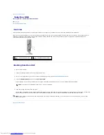
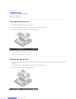
1 Port 1
–
mouse selective USB
port
2 Port 0
–
keyboard selective USB
port
NOTE:
If a mouse is not attached to USB port 1, the port is disabled.
NOTE:
If you disconnect a device from the selective USB port, the port becomes disabled. To re-enable the port, connect the device, power off, and
reboot the system.


