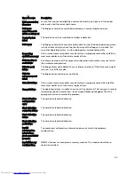
background image

Error Message

Description

please populate 
DIMM1

Keyboard failure

A cable or connector may be loose, or the keyboard or keyboard/mouse 
controller may be faulty.

Memory address 
line failure at 
address, read 
value expecting 
value

A memory module may be faulty or improperly seated. Reinstall the memory 
modules and, if necessary, replace them.

Memory allocation 
error

The software you are attempting to run is conflicting with the operating system, 
another program, or a utility.

Memory data line 
failure at address, 
read value 
expecting value

A memory module may be faulty or improperly seated. Reinstall the memory 
modules and, if necessary, replace them.

Memory double 
word logic failure 
at address, read 
value expecting 
value

A memory module may be faulty or improperly seated. Reinstall the memory 
modules and, if necessary, replace them.

Memory odd/even 
logic failure at 
address, read 
value expecting 
value

A memory module may be faulty or improperly seated. Reinstall the memory 
modules and, if necessary, replace them

Memory write/
read failure at 
address, read 
value expecting 
value

A memory module may be faulty or improperly seated. Reinstall the memory 
modules and, if necessary, replace them.

Memory size in 
CMOS invalid

The amount of memory recorded in the computer configuration information does 
not match the memory installed in the computer.

Memory tests 
terminated by 
keystroke

A keystroke interrupted the memory test.

No boot device 
available

The computer cannot find the floppy disk or hard drive.

No boot sector on 
hard-disk drive

The computer configuration information in System Setup may be incorrect.

No timer tick 
interrupt

A chip on the system board might be malfunctioning.

54

Summary of Contents for OptiPlex 3020

Page 1: ...Dell OptiPlex 3020 Small Form Factor Owner s Manual Regulatory Model D08S Regulatory Type D08S001 ...

Page 2: ...registered trademarks or trademarks of Intel Corporation in the U S and other countries AMD is a registered trademark and AMD Opteron AMD Phenom AMD Sempron AMD Athlon ATI Radeon and ATI FirePro are trademarks of Advanced Micro Devices Inc Microsoft Windows MS DOS Windows Vista the Windows Vista start button and Office Outlook are either trademarks or registered trademarks of Microsoft Corporation...

Page 3: ...alling the Optical Drive 15 Removing the Drive Cage 15 Installing the Drive Cage 16 Removing the Hard Drive 17 Installing the Hard Drive 18 Removing the Speaker 18 Installing the Speaker 19 Memory Module Guidelines 19 Removing the Memory 20 Installing the Memory 20 Removing the System Fan 20 Installing the System Fan 21 Removing the Power Switch 21 Installing the Power Switch 22 Removing the I O P...

Page 4: ...tup Options 36 Updating the BIOS 44 Clearing Forgotten Password 45 Clearing CMOS 45 System and Setup Password 45 Assigning a System Password and Setup Password 46 Deleting or Changing an Existing System and or Setup Password 46 Disabling a System Password 47 4 Diagnostics 49 Enhanced Pre Boot System Assessment ePSA Diagnostics 49 5 Troubleshooting Your Computer 51 Power LED Diagnostics 51 Beep Cod...

Page 5: ... electrostatic discharge ground yourself by using a wrist grounding strap or by periodically touching an unpainted metal surface such as a connector on the back of the computer CAUTION Handle components and cards with care Do not touch the components or contacts on a card Hold a card by its edges or by its metal mounting bracket Hold a component such as a processor by its edges not by its pins CAU...

Page 6: ...erating system In Windows 8 Using a touch enabled device a Swipe in from the right edge of the screen opening the Charms menu and select Settings b Select the and then select Shut down Using a mouse a Point to upper right corner of the screen and click Settings b Click the and select Shut down In Windows 7 1 Click Start 2 Click Shut Down or 1 Click Start 2 Click the arrow in the lower right corner...

Page 7: ...nd then plug it into the computer 2 Connect any telephone or network cables to your computer 3 Connect your computer and all attached devices to their electrical outlets 4 Turn on your computer 5 If required verify that the computer works correctly by running the Dell Diagnostics 7 ...

Page 8: ...8 ...

Page 9: ...ent may require the following tools Small flat blade screwdriver Phillips screwdriver Small plastic scribe System Overview The figure below displays the inside view of the Small Form Factor after the base cover has been removed The call outs show the names and the layout of the components inside the computer Inside view 1 optical drive 2 front bezel 3 power supply unit 4 expansion card 9 ...

Page 10: ... 1 front I O 2 system fan 3 system board 4 memory module 5 coin cell 6 speaker Removing the Cover 1 Follow the procedures in Before Working Inside Your Computer 2 Remove the thumbscrews that secure the cover to the computer Slide the cover from the computer 10 ...

Page 11: ...stalling the Cover 1 Place the cover on the computer 2 Slide the computer cover towards the front of the chassis until it is fully engaged 3 Tighten the thumbscrew in clockwise direction to secure the computer cover 4 Follow the procedures in After Working Inside Your Computer 11 ...

Page 12: ...he front bezel from the computer Installing the Front Bezel 1 Insert the hooks along the bottom edge of the front bezel into the slots on the chassis front 2 Push the bezel toward the computer to engage the front bezel retention clips until they click into place 3 Install the cover 4 Follow the procedures in After Working Inside Your Computer Removing The Expansion Card 1 Follow the procedures in ...

Page 13: ...ps as shown in the illustration a Pull the release lever away from the expansion card until you release the securing tab from the dent in the card 1 b Ease the card up and out of its connector and remove it from the computer 2 13 ...

Page 14: ...tall the cover 3 Follow the procedures in After Working Inside Your Computer Removing the Optical Drive 1 Follow the procedures in Before Working Inside Your Computer 2 Remove the cover 3 Disconnect the data and power cables from the back of the optical drive 4 Lift the tab and slide the optical drive out to remove it from the computer 14 ...

Page 15: ...racket 2 Slide the optical drive to insert it into the drive cage 3 Connect the data and power cables to the optical drive 4 Install the cover 5 Follow the procedures in After Working Inside Your Computer Removing the Drive Cage 1 Follow the procedures in Before Working Inside Your Computer 2 Remove the a cover b front bezel c optical drive 3 Disconnect the data and the power cables from the back ...

Page 16: ...f the computer to allow access to the cable connectors on the hard drive 2 Connect the data and power cables to the back of the hard drive 3 Flip over the drive cage and insert it into the chassis The drive cage tabs are secured by the slots in the chassis 4 Slide the drive cage handle toward the locked position 5 Install the a front bezel b optical drive c cover 16 ...

Page 17: ...rform the following steps as shown in the illustration and a Press the retention clips inwards 1 b Slide the hard drive bracket out from the drive cage 2 4 Flex the hard drive bracket and remove the hard drive from the bracket 5 Remove the screws that secure the mini hard drive to the hard drive bracket and remove the hard drive from its bracket NOTE Perform step 5 only if you have a mini hard dri...

Page 18: ...ocedures in After Working Inside Your Computer Removing the Speaker 1 Follow the procedures in Before Working Inside Your Computer 2 Remove a cover b optical drive c drive cage 3 Perform the following steps as shown in the illustration a Disconnect the speaker cable from the system board 1 b Release it from the securing tab inside the chassis 2 4 Perform the following steps as shown in the illustr...

Page 19: ...e following general guidelines when configuring your system memory Memory modules of different sizes can be mixed for example 2 GB and 4 GB But all populated channels must have identical configurations Memory modules must be installed beginning with the first socket NOTE The memory sockets in your computer may be labeled differently depending on the hardware configuration For example A1 A2 or 1 2 ...

Page 20: ... to secure them in place 3 Install the cover 4 Follow the procedures in After Working Inside Your Computer Removing the System Fan 1 Follow the procedures in Before Working Inside Your Computer 2 Remove a cover b optical drive c drive cage d front bezel 3 Perform the following steps as shown in the illustration a Press the system fan cable 1 b Disconnect the system fan cable from the system board ...

Page 21: ...front bezel b drive cage c optical drive d cover 5 Follow the procedures in After Working Inside Your Computer Removing the Power Switch 1 Follow the procedures in Before Working Inside Your Computer 2 Remove the a cover b front bezel c optical drive d drive cage 3 Perform the following steps as shown in the illustration a Disconnect the power switch cable from the system board b Unroute the cable...

Page 22: ...ower switch 1 b Release it from the chassis 2 c Remove the power switch along with its cable from the computer Installing the Power Switch 1 Slide the power switch in through the front of the computer 2 Connect the power switch cable to the system board 3 Install the a drive cage b optical drive 22 ...

Page 23: ...c drive cage d front bezel 3 Perform the following steps as shown in the illustration a Disconnect the I O cable the computer 1 b Disconnect the audio cable the computer 2 c Disconnect the HDD LED cable the computer 3 4 Perform the following steps as shown in the illustration a Remove the screw that secures the I O panel to the chassis 1 b Slide the I O panel to release and remove it from the comp...

Page 24: ...the a drive cage b optical drive c front bezel d cover 6 Follow the procedures in After Working Inside Your Computer Removing the Power Supply 1 Follow the procedures in Before Working Inside Your Computer 2 Remove a cover b front bezel c optical drive d drive cage 3 Perform the following steps as shown in the illustration a Press the 8 pin and 4 pin power cable 1 b Disconnect the 8 pin and 4 pin ...

Page 25: ...4 Release the blue latch from the system 5 Remove the screws that secure the power supply to the back of the computer 25 ...

Page 26: ...m the following steps as shown in the illustration a Press the latch downwards to release the power supply unit 1 b Slide the power supply unit from the computer 2 7 Lift the power supply out of the computer 26 ...

Page 27: ...rd 4 Thread the power cables into the chassis clips 5 Install a drive cage b optical drive c front bezel d cover 6 Follow the procedures in After Working Inside Your Computer Removing the Coin Cell Battery 1 Follow the procedures in Before Working Inside Your Computer 2 Remove the a cover b front bezel c drive cage 3 Press the release latch away from the battery to allow it to pop up from the sock...

Page 28: ... Working Inside Your Computer Removing the Heatsink Assembly 1 Follow the procedures in Before Working Inside Your Computer 2 Remove the cover 3 Using both hands push away the two release handles while lifting the fan shroud upward and off the computer 4 Perform the following steps as shown in the illustration a Press the fan cable 1 b Disconnect the fan cable from the system board 2 c Loosen the ...

Page 29: ...n and push to click in place 5 Install the cover 6 Follow the procedures in After Working Inside Your Computer Removing the Processor 1 Follow the procedures in Before Working Inside Your Computer 2 Remove the cover 3 Remove the heat sink assembly 4 Press the release lever down and then move it outward to release it from the retention hook Lift the processor cover and remove the processor from the...

Page 30: ... the Intrusion Switch 1 Follow the procedures in Before Working Inside Your Computer 2 Remove the a cover b heat sink assembly 3 Disconnect the intrusion switch cable from the system board 4 Slide the intrusion switch toward the bottom of the chassis and remove it from the computer Installing the Intrusion Switch 1 Insert the intrusion switch into the chassis rear and slide it outward to secure it...

Page 31: ...onnector 6 processor socket 7 CPU fan connector 8 memory module connectors 9 HDD LED chassis detect connector 10 power switch connector 11 coin cell battery 12 system power connector 13 system fan connector 14 RTC reset jumper 15 ODD SATA connector 16 HDD SATA connector 17 power connector 18 front i o connector 19 internal speaker connector 20 password reset jumper 21 front audio connector 31 ...

Page 32: ...ve the a cover b front bezel c optical drive d drive cage e memory f heat sink assembly g expansion card s h power supply 3 Disconnect all the cables connected to the system board and move the cables away from the chassis 4 Turn the hex screw counter clockwise and remove from the system board 32 ...

Page 33: ...5 Lift the cover upward to a 45 degree angle and remove it from the computer 6 Remove the system board from the chassis 33 ...

Page 34: ...tem board in the chassis 2 Tighten the screws securing the system board to the chassis 3 Connect the cables to the system board 4 Install the a power supply b expansion card s c heat sink assembly d memory e drive cage f optical drive g front bezel h cover 5 Follow the procedures in After Working Inside Your Computer 34 ...

Page 35: ...on Self Test POST when the Dell logo appears you can Access System Setup by pressing F2 key Bring up the one time boot menu by pressing F12 key The one time boot menu displays the devices that you can boot from including the diagnostic option The boot menu options are Removable Drive if available STXXXX Drive NOTE XXX denotes the SATA drive number Optical Drive Diagnostics NOTE Choosing Diagnostic...

Page 36: ...any unsaved changes and restarts the system F1 Displays the System Setup help file System Setup Options NOTE Depending on your computer and its installed devices the items listed in this section may or may not appear Table 2 General Option Description System Board This section lists the primary hardware features of your computer System Information Memory Information PCI Information Processor Infor...

Page 37: ...led w Cloud Desktop Serial Port Identifies and defines the serial port settings You can set the serial port to Disabled Default COM1 COM2 COM3 COM4 NOTE The operating system may allocate resources even if the setting is disabled SATA Operation Allows you to configure the internal SATA hard drive controller The options are Disabled ATA AHCI Default Drives Allows you to enable or disable the various...

Page 38: ...Display Table 5 Security Option Description Admin Password This field lets you set change or delete the administrator admin password sometimes called the setup password The admin password enables several security features The drive does not have a password set by default Enter the old password Enter the new password Confirm the new password System Password This field lets you set change or delete ...

Page 39: ...m will always prompt for passwords on any module bay HDDs that may be present Password Change Allows you to determine whether changes to the system and hard disk passwords are permitted when an administrator password is set Allow Non Admin Password Changes This option is enabled by default TPM Security This option lets you control whether the Trusted Platform Module TPM in the system is enabled an...

Page 40: ...ure Boot Enable Allows you to enable or disable the Secure Boot Feature The options are Disabled Default Enabled Expert Key Management Allows you to manipulate the security key databases only if the system is in Custom Mode The Enable Custom Mode option is disabled by default The options are PK KEK db dbx If you enable the Custom Mode the relevant options for PK KEK db and dbx appear The options a...

Page 41: ...processor sleep states Default Setting Enabled Limit CPUID Value This field limits the maximum value the processor Standard CPUID Function will support Disable CPUID Limit NOTE Some Operating system will not complete installation when the maximum CPUID Function is greater than 3 HyperThread control SFF Allows you to enable or disable the Hyper Threading Technology This option is enabled by default...

Page 42: ...sabled Does not allow the system to power on by special LAN signals when it receives a wake up signal from the LAN or wireless LAN LAN Only Allows the system to be powered on by special LAN signals LAN or PXE Boot Allows the system to be powered on by special LAN or PXE Bootsignals For Ultra Small Form Factor only This option is Disabled by default Block Sleep Allows you to block entering to sleep...

Page 43: ...mageServer Server IP Address Specifies the primary static IP address of the ImageServer with which the client software communicates The default IP address is 255 255 255 255 NOTE This field is only relevant when the Integrated NIC control in the System Configuration group is set to Enabled with ImageServer and when Lookup Method is set to Static IP Server Port Specifies the primary IP port of the ...

Page 44: ...ear the log Clear Log Updating the BIOS It is recommended to update your BIOS system setup on replacing the system board or if an update is available For laptops ensure that your computer battery is fully charged and connected to a power outlet 1 Re start the computer 2 Go to dell com support 3 Enter the Service Tag or Express Service Code and click Submit NOTE To locate the Service Tag click Wher...

Page 45: ...he cover 9 Replace the jumper on the pins 2 and 3 10 Install the cover 11 Follow the procedures in After Working Inside Your Computer 12 Power on the computer 13 Go to the system setup and assign a new system or setup password Clearing CMOS 1 Follow the procedures in Before Working Inside Your Computer 2 Remove the cover 3 Remove the PCI card if installed 4 Identify the CMOS jumper on the system b...

Page 46: ...ystem Setup screen select System Security and press Enter The System Security screen appears 2 In the System Security screen verify that Password Status is Unlocked 3 Select System Password enter your system password and press Enter or Tab Use the following guidelines to assign the system password A password can have up to 32 characters The password can contain the numbers 0 through 9 Only lower c...

Page 47: ...de a system password and a setup password The password jumper disables any password s currently in use NOTE You can also use the following steps to disable a forgotten password 1 Follow the procedures in Before Working on Your Computer 2 Remove the cover 3 Identify the PSWD jumper on the system board 4 Remove the PSWD jumper from the system board NOTE The existing passwords are not disabled erased...

Page 48: ...48 ...

Page 49: ... provide extra information about the failed device s View status messages that inform you if tests are completed successfully View error messages that inform you of problems encountered during testing CAUTION Use the system diagnostics to test only your computer Using this program with other computers may cause invalid results or error messages NOTE Some tests for specific devices require user int...

Page 50: ...50 ...

Page 51: ...links short pause 3 amber blinks followed by long pause then repeats Table 14 Power LED Diagnostics Amber LED State White LED State Description off off system is OFF off breathing system is in sleep state blinking off power supply unit PSU failure steady off PSU is working but failed to fetch code off steady system is ON Amber LED State Description 2 1 system board failure 2 2 system board PSU or ...

Page 52: ... 2 If the system does have an internal speaker connect an external speaker to line out connection to hear the beep sound NOTE User can also check the power LED behavior instead of the beep code for troubleshooting purpose Error Messages Error Message Description Address mark not found The BIOS found a faulty disk sector or could not find a particular disk sector Alert Previous attempts at booting ...

Page 53: ...ette read failure The floppy disk may be defective or a cable may be loose If the drive access light turns on try a different disk Diskette subsystem reset failed The floppy drive controller may be faulty Gate A20 failure One or more memory modules may be faulty or improperly seated Reinstall the memory modules and if necessary replace them General failure The operating system is unable to carry o...

Page 54: ...e faulty or improperly seated Reinstall the memory modules and if necessary replace them Memory odd even logic failure at address read value expecting value A memory module may be faulty or improperly seated Reinstall the memory modules and if necessary replace them Memory write read failure at address read value expecting value A memory module may be faulty or improperly seated Reinstall the memo...

Page 55: ...the floppy or hard drive Seek error The operating system cannot find a specific track on the floppy disk or hard drive Shutdown failure A chip on the system board might be malfunctioning Time of day clock stopped The battery might be dead Time of day not set please run the System Setup program The time or date stored in System Setup does not match the computer clock Timer chip counter 2 failed A c...

Page 56: ...ription drive by calling your support desk or Dell Write fault The operating system cannot write to the floppy or hard drive Write fault on selected drive The operating system cannot write to the floppy or hard drive 56 ...

Page 57: ...Core I5 4570 Processor Quad Core 3 20GHz Turbo 6MB w HD Graphics 4600 Core i3 4130 Processor Dual Core 3 4GHz 3MB w HD Graphics 4400 Pentium G3220 Processor Dual Core 3 0GHz 3MB w HD Graphics Cache Core I5 4570 Processor 6MB Core i3 4130 Processor 3MB Pentium G3220 Processor 3MB Table 16 System Information Feature Specification Chipset Intel H81 Chipset BIOS chip NVRAM 64Mbit 8MB Table 17 Memory F...

Page 58: ...Gbps PCIex1 support gen 2 5Gbps Table 23 Drives Feature Specification Externally accessible ODD is externally accessible Internally accessible HDD is internally accessible Table 24 External Connectors Feature Specification Audio Line in MIC Line out port on rear side and MIC HP on front I O side Front Panel USB2 0 2 and MIC 1 HP 1 supported on front panel Back Panel VGA 1 DP 1 RJ45 1 USB3 0 2 USB2...

Page 59: ...button light White light Solid white light indicates power on state Breathing white light indicates sleep state of the computer Drive activity light White light Blinking white light indicates that the computer is reading data from or writing data to the hard drive Back of the computer Link integrity light on integrated network adapter Green a good 10 Mbps connection exists between the network and ...

Page 60: ...ble 28 Physical Feature Specification Physical 8 38 liters Height 290 mm Width 92 6 mm Depth 312 mm Weight 5 Kgs Table 29 Environmental Feature Specification Temperature Operating 0 degree to 35 degree Storage 40 degree to 65 degree Relative humidity maximum Operating 20 R H to 80 R H Storage 20 R H to 95 R H Maximum vibration Operating 0 26Grms Storage 1 37Grms Maximum shock Operating 40G 2ms Sto...

Page 61: ...Feature Specification Airborne contaminant level G1 or lower as defined by ANSI ISA S71 04 1985 61 ...

Page 62: ...62 ...

Page 63: ...ome services may not be available in your area To contact Dell for sales technical support or customer service issues 1 Go to dell com contactdell 2 Verify your country or region from the drop down menu at the top left corner of the page 3 Select your support category Technical Support Customer Support Sales or International Support Services 4 Select the appropriate service or support link based o...

Reviews: