


After working inside your computer
.
Cover
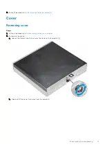
Removing cover
Steps
Before working inside your computer
.
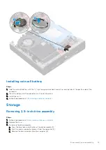
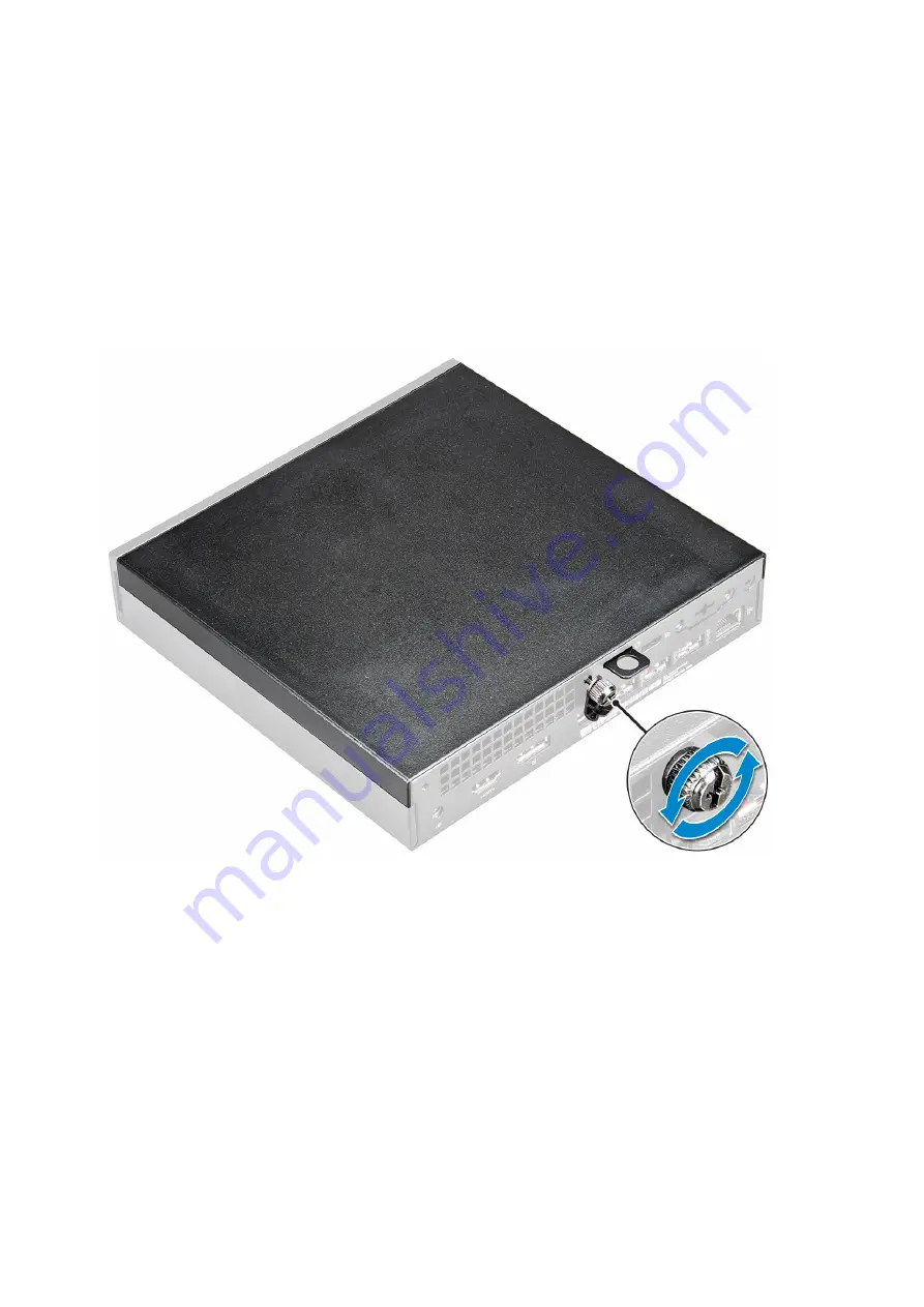
2. To remove the cover:
a. Loosen the thumbscrew that secures the cover to the computer [1].
b. Slide and lift the cover to remove from the computer.
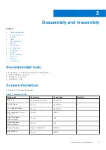
Disassembly and reassembly
11


