

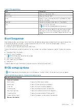
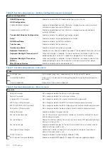

Table 13. System setup options—Wireless menu
Wireless
Wireless Switch
Determine which wireless devices can be controlled by the Wireless Switch.
Wireless Device Enable
Enable or disable internal wireless devices.
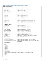
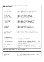
Table 14. System setup options—Maintenance menu
Maintenance
Service Tag
Display the system’s Service Tag.
Asset Tag
Create a system Asset Tag.
BIOS Downgrade
Control flashing of the system firmware to previous revisions.
Data Wipe
Enable to securely erase data from all internal storage devices.
BIOS Recovery
Enable the user to recover from certain corrupted BIOS conditions from a
recovery file on the user primary hard drive or an external USB key.
First Power On Date
Set Ownership Date
Table 15. System setup options—System Logs menu
System Logs
BIOS Events
Display BIOS events.
Thermal Events
Display Thermal events.
Power Events
Display Power events.
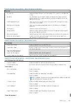
Table 16. System setup options—SupportAssist System Resolution menu
SupportAssist System Resolution
Auto OS Recovery Threshold
Control the automatic boot flow for SupportAssist System Resolution Console
and for Dell OS Recovery tool.
SupportAssist OS Recovery
Enable or disable the boot flow for SupportAssist OS Recovery tool in the even
of certain system errors.
BIOSConnect
Enable or disable BIOSConnect
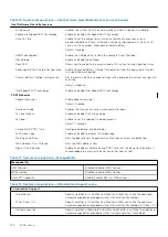
Updating the BIOS in Windows
Prerequisites
It is recommended to update your BIOS (System Setup), when you replace the system board or if an update is available. For
laptops, ensure that your computer battery is fully charged and connected to a power outlet.
About this task
NOTE:
If BitLocker is enabled, it must be suspended before updating the system BIOS, and then re-enabled after the BIOS
update is completed.
Steps
1. Restart the computer.
2. Go to
.
●
Enter the
Service Tag
or
Express Service Code
and click
Search
.
●
Click
Drivers & Downloads
.
●
Click
Detect Drivers
and follow the on-screen instructions.
3. If you are unable to detect or find the Service Tag, click
Browse all products
.
4. Choose the appropriate category to reach the product page.
BIOS setup
125
Summary of Contents for OptiPlex 7760
Page 1: ...Precision 7760 Service Manual Regulatory Model P44E Regulatory Type P44E002 July 2021 Rev A01 ...
Page 17: ...For computers without SSD door configuration Removing and installing components 17 ...
Page 25: ...Removing and installing components 25 ...
Page 29: ...Removing and installing components 29 ...
Page 74: ...74 Removing and installing components ...
Page 87: ...Removing and installing components 87 ...
Page 97: ...Removing and installing components 97 ...
Page 98: ...98 Removing and installing components ...


