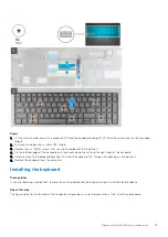
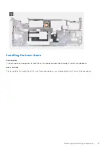
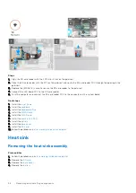
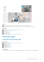
About this task
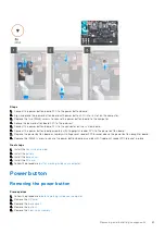
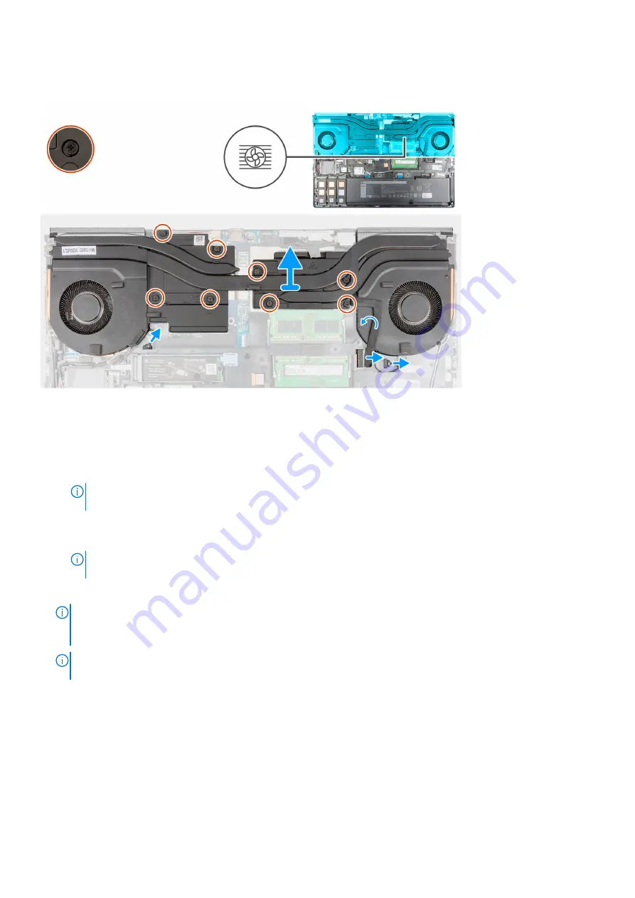
The figure indicates the location of the heat-sink assembly and provides a visual representation of the removal procedure.
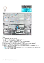
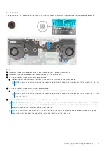
Steps
1. Disconnect the power-adapter cable and peel the cable from the heat-sink assembly.
2. Disconnect the two fan cables from the connectors on the system board.
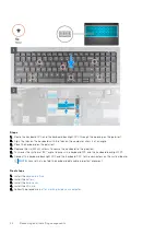
3. For the computers shipped with UMA graphics card:
a. Loosen the four captive screws that secure the heat-sink assembly to the system board.
NOTE:
Loosen the captive screws in the order stamped onto the heat-sink assembly next to the screws [4 > 3 > 2 >
1].
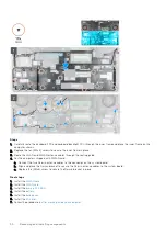
4. For the computers shipped with discrete graphics card:
a. Loosen the eight captive screws that secure the heat-sink assembly to the system board.
NOTE:
Loosen the captive screws in the order stamped onto the heat-sink assembly next to the screws [8 > 7 > 6 >
5 > 4 > 3 > 2 > 1].
5. Carefully lift the heat-sink assembly to remove it from the computer.
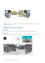
NOTE:
While lifting the heat-sink assembly, the thermal pads attached to the bottom side of the heat sink can stick to
the computer and can cause only one side to lift. As the heat sink thermal tube is thin and can bend easily, ensure to
evenly lift the heat-sink assembly and not from one side.
NOTE:
If any thermal pads attached to the bottom side of the heat-sink assembly are detached while removing the
heat-sink assembly, adhere them back to their correct location on the heat sink.
Removing and installing components
57
Summary of Contents for OptiPlex 7760
Page 1: ...Precision 7760 Service Manual Regulatory Model P44E Regulatory Type P44E002 July 2021 Rev A01 ...
Page 17: ...For computers without SSD door configuration Removing and installing components 17 ...
Page 25: ...Removing and installing components 25 ...
Page 29: ...Removing and installing components 29 ...
Page 74: ...74 Removing and installing components ...
Page 87: ...Removing and installing components 87 ...
Page 97: ...Removing and installing components 97 ...
Page 98: ...98 Removing and installing components ...


