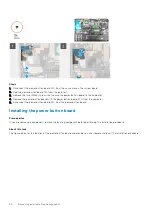
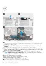
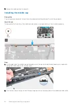
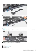
12. Remove the
.
13. Remove the
.
14. Remove the
.
15. Remove the
.
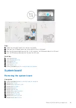
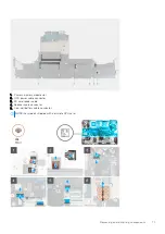
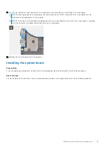
About this task
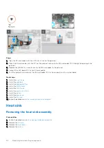
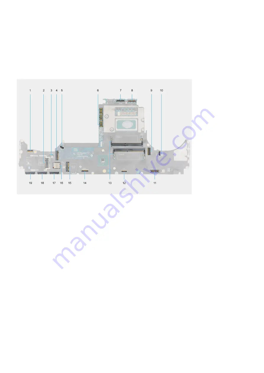
The figure indicates the location of the system board and provides a visual representation of the removal procedure.
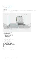
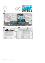
The following image indicates the connectors on your system board:
1. Power button FFC connector
2. WWAN card connector
3. Darwin antenna cable connector
4. Secondary M.2 SSD connector
5. Fan cable connector
6. FPC beam connector
7. Display cable connector
8. IR camera/Touchscreen cable connector
9. Power-adapter port connector
10. Fan cable connector
11. Battery cable connector
12. Touchpad cable cpnnector
13. Secondary memory module slot
14. USH daughter board cable connector
15. WLAN card connector
16. SIM card slot
17. Primary M.2 SSD slot 3 connector
18. Primary M.2 SSD slot 4 connector
19. Primary M.2 SSD slot 5 connector
70
Removing and installing components
Summary of Contents for OptiPlex 7760
Page 1: ...Precision 7760 Service Manual Regulatory Model P44E Regulatory Type P44E002 July 2021 Rev A01 ...
Page 17: ...For computers without SSD door configuration Removing and installing components 17 ...
Page 25: ...Removing and installing components 25 ...
Page 29: ...Removing and installing components 29 ...
Page 74: ...74 Removing and installing components ...
Page 87: ...Removing and installing components 87 ...
Page 97: ...Removing and installing components 97 ...
Page 98: ...98 Removing and installing components ...


