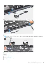
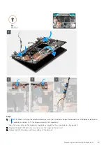
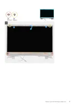
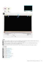
Steps
1. Remove the two (M2.5x2.5) screws and the two (M2x2.5) screws that secure the display panel to the display assembly.
2. Lift the display panel and turn the display panel over to access the display cable.
3. Peel the conductive tape covering the display cable.
4. Peel the adhesive tapes that secure the display cable connector.
5. Peel the adhesive rubber strip covering the display cable connector.
6. Unlock the display cable connector and then disconnect the display cable from the back of the display panel.
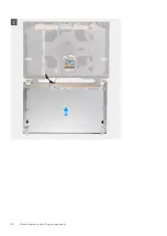
7. Remove the display panel form the display assembly.
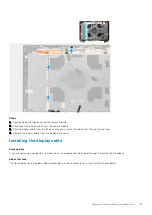
8. Remove the display panel.
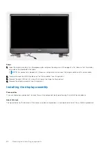
NOTE:
The support brackets attached to the display panel are defined as a single service assembly part and cannot be
further disassembled.
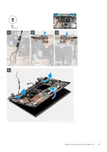
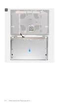
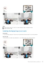
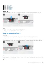
Installing the display panel (non-touch)
Prerequisites
If you are replacing a component, remove the existing component before performing the installation procedure.
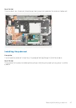
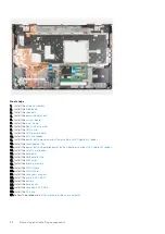
About this task
The figure indicates the display panel and provides a visual representation of the installation procedure.
Removing and installing components
99
Summary of Contents for OptiPlex 7760
Page 1: ...Precision 7760 Service Manual Regulatory Model P44E Regulatory Type P44E002 July 2021 Rev A01 ...
Page 17: ...For computers without SSD door configuration Removing and installing components 17 ...
Page 25: ...Removing and installing components 25 ...
Page 29: ...Removing and installing components 29 ...
Page 74: ...74 Removing and installing components ...
Page 87: ...Removing and installing components 87 ...
Page 97: ...Removing and installing components 97 ...
Page 98: ...98 Removing and installing components ...


