


Dell OptiPlex G1 Managed PC Systems Documentation Update15
6\VWHP%RDUGDQG&RQQHFWRUV
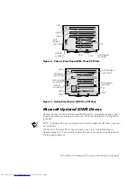
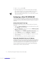
New OptiPlex G1 systems contain the system board shown in Figure 4.
)LJXUH6\VWHP%RDUG)HDWXUHV
SEC cartridge connector
(SLOT1)
microprocessor
fan connector (FAN)
video
connector (MONITOR)
serial port 2
connector
(SERIAL2)
USB connectors
(USB) (2)
parallel/serial port 1
connectors (stacked)
(PARALLEL/SERIAL1)
mouse/keyboard
connectors (stacked)
(MOUSE/KYBD)
video-memory
upgrade socket
(VIDEO_UPGRADE)
control panel
connector (PANEL)
battery socket
(BATTERY)
optional
integrated NIC
connector (ENET)
riser board connector
(RISER)
system board jumpers
primary EIDE
interface connector
(IDE1) (pin-1 corner)
secondary EIDE
interface connector
(IDE2) (pin-1 corner)
front of computer
diskette/tape drive
interface connector
(DSKT) (pin-1 corner)
DIMM sockets (2)
(DIMM_ADIMM_B)
main power input
connector (POWER_1)
3.3-V power input
connector (POWER_2)
ATI multimedia
connector (AMC)
chassis intrusion-
switch connector


