


7-2
Dell OptiPlex G1 Mini Tower Managed PC Reference and Installation Guide
5HPRYLQJDQG5HSODFLQJWKH)URQW%H]HO
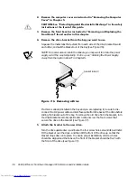
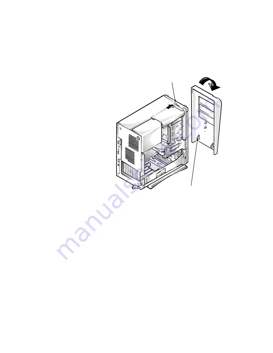
The bezel is secured to the front of the chassis by two tabs and two hooks. The tab
release for the bezel is at the top of the computer chassis and can be accessed only
with the computer cover removed (see “Removing the Computer Cover” in Chap-
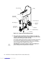
ter 5). With the cover removed, release the bezel by pressing the tab release marked
with the icon (see Figure 7-2).
)LJXUH5HPRYLQJWKH)URQW%H]HO
While pressing the tab release, tilt the bezel away from the chassis, disengage the
two retaining hooks at the bottom of the bezel, and carefully pull the bezel away from
the chassis.
To replace the bezel, fit the two retaining hooks on the bezel into their corresponding
slots at the bottom of the chassis. Then rotate the top of the bezel toward the chassis
until the top tabs snap into their corresponding slots on the bezel.
5HPRYLQJDQG5HSODFLQJ)URQW3DQHO
,QVHUWV
Empty drive bays contain a front-panel insert to protect the inside of the computer
from dust particles and also to ensure proper airflow within the computer. Before you
install a drive in an empty drive bay, you must first remove the front-panel insert.
tab release
retaining hooks (2)
Summary of Contents for OptiPlex G1
Page 1: ... ZZZ GHOO FRP HOO 2SWL3OH 0LQL 7RZHU 0DQDJHG 3 6 VWHPV 5 5 1 1 167 7 21 8 ...
Page 8: ...x ...
Page 20: ...xxii ...
Page 34: ...1 14 Dell OptiPlex G1 Mini Tower Managed PC Reference and Installation Guide ...
Page 56: ...2 22 Dell OptiPlex G1 Mini Tower Managed PC Reference and Installation Guide ...
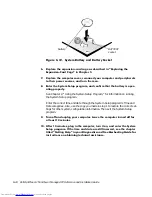
Page 89: ...Working Inside Your Computer 5 9 LJXUH 6 VWHP RDUG XPSHUV jumpered unjumpered ...
Page 128: ...7 16 Dell OptiPlex G1 Mini Tower Managed PC Reference and Installation Guide ...
Page 134: ...A 6 Dell OptiPlex G1 Mini Tower Managed PC Reference and Installation Guide ...
Page 156: ...D 4 Dell OptiPlex G1 Mini Tower Managed PC Reference and Installation Guide ...


