


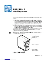


Installing Drives
7-3
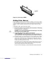
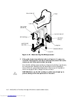
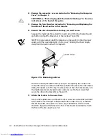
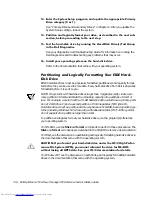
To remove the insert covering a 5.25-inch bay, follow these steps:
7XUQRIIWKHV\VWHPLQFOXGLQJDQ\DWWDFKHGSHULSKHUDOVDQGGLVFRQQHFW
DOOWKHDOWHUQDWLQJFXUUHQW$&SRZHUFDEOHVIURPWKHLUSRZHUVRXUFHV
5HPRYHWKHFRPSXWHUFRYHUDVLQVWUXFWHGLQ´5HPRYLQJWKH&RPSXWHU
&RYHUµLQ&KDSWHU
&$87,216HH´3URWHFWLQJ$JDLQVW(OHFWURVWDWLF'LVFKDUJHµLQWKHVDIHW\
LQVWUXFWLRQVDWWKHIURQWRIWKLVJXLGH
5HPRYHWKHIURQWEH]HODVLQVWUXFWHGLQWKHSUHYLRXVVHFWLRQ´5HPRY
LQJDQG5HSODFLQJWKH)URQW%H]HOµ
:LWK\RXUWKXPEVSUHVVLQHDFKHQGRIWKHLQVHUWXQWLOLWVQDSVIUHHRI
WKHEH]HOVHH)LJXUH
)LJXUH5HPRYLQJWKH)URQW3DQHO,QVHUWIRUD,QFK%D\
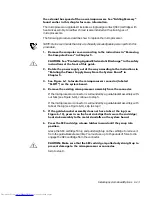
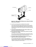
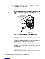
To replace a front-panel insert for a 5.25-inch bay, work
from inside the bezel. Insert
the two ring-tabs (one on each end of the insert) over the posts on the inside of the
bay opening, and firmly press both ends of the insert into place (see Figure 7-3).
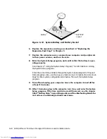
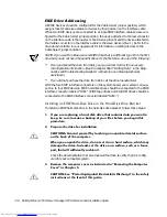
&RQQHFWLQJ'ULYHV
When installing a drive, you connect two cables—a direct current (DC) power cable
and an interface cable—to the back of the drive. Your drive’s power input connector
(to which you connect the DC power cable) resembles the connector shown in
Figure 7-4.
posts (2)
computer
cover
ring-tabs (2)
Summary of Contents for OptiPlex G1
Page 1: ... ZZZ GHOO FRP HOO 2SWL3OH 0LQL 7RZHU 0DQDJHG 3 6 VWHPV 5 5 1 1 167 7 21 8 ...
Page 8: ...x ...
Page 20: ...xxii ...
Page 34: ...1 14 Dell OptiPlex G1 Mini Tower Managed PC Reference and Installation Guide ...
Page 56: ...2 22 Dell OptiPlex G1 Mini Tower Managed PC Reference and Installation Guide ...
Page 89: ...Working Inside Your Computer 5 9 LJXUH 6 VWHP RDUG XPSHUV jumpered unjumpered ...
Page 128: ...7 16 Dell OptiPlex G1 Mini Tower Managed PC Reference and Installation Guide ...
Page 134: ...A 6 Dell OptiPlex G1 Mini Tower Managed PC Reference and Installation Guide ...
Page 156: ...D 4 Dell OptiPlex G1 Mini Tower Managed PC Reference and Installation Guide ...


