


7-4
Dell OptiPlex G1 Mini Tower Managed PC Reference and Installation Guide
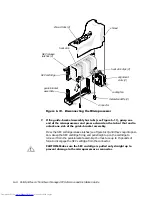
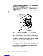
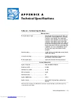
)LJXUH'&3RZHU&DEOH&RQQHFWRU
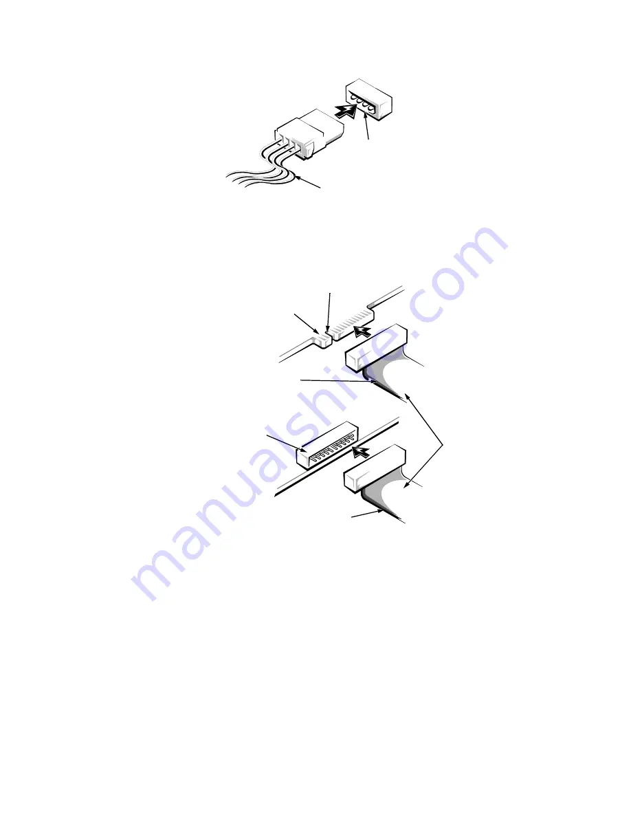
The drive’s interface connector is a card-edge connector or a header connector, as
shown in Figure 7-5.
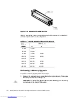
)LJXUH'ULYH,QWHUIDFH&RQQHFWRUV
When attaching the interface cable to a drive, be sure to match the colored strip on
the cable to pin 1 of the drive’s interface connector. For the location of pin 1 on the
drive’s interface connector, see the documentation that came with the drive.
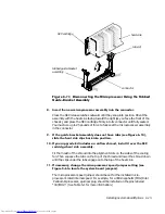
When disconnecting an interface cable from the system board, be sure to press in on
the locking tabs on the cable connector before disconnecting the cable. When attach-
ing an interface cable to the system board, be sure that the locking tabs snap into
place, ensuring that the cable is firmly attached to the connector on the system board.
power input
connector
DC power cable
header
connector
on drive
interface
cables
colored strip
notch
colored strip
card-edge
connector
on drive
Summary of Contents for OptiPlex G1
Page 1: ... ZZZ GHOO FRP HOO 2SWL3OH 0LQL 7RZHU 0DQDJHG 3 6 VWHPV 5 5 1 1 167 7 21 8 ...
Page 8: ...x ...
Page 20: ...xxii ...
Page 34: ...1 14 Dell OptiPlex G1 Mini Tower Managed PC Reference and Installation Guide ...
Page 56: ...2 22 Dell OptiPlex G1 Mini Tower Managed PC Reference and Installation Guide ...
Page 89: ...Working Inside Your Computer 5 9 LJXUH 6 VWHP RDUG XPSHUV jumpered unjumpered ...
Page 128: ...7 16 Dell OptiPlex G1 Mini Tower Managed PC Reference and Installation Guide ...
Page 134: ...A 6 Dell OptiPlex G1 Mini Tower Managed PC Reference and Installation Guide ...
Page 156: ...D 4 Dell OptiPlex G1 Mini Tower Managed PC Reference and Installation Guide ...


