


7-8
Dell OptiPlex G1 Mini Tower Managed PC Reference and Installation Guide
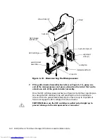
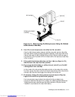
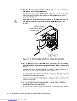
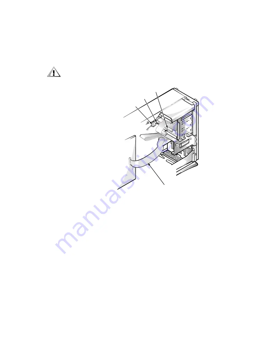
&RQQHFWWKHDSSURSULDWHLQWHUIDFHFDEOHWRWKHLQWHUIDFHFRQQHFWRURQ
WKHEDFNRIWKHGULYHVHH)LJXUH
If your system came with an EIDE CD-ROM or tape drive, use the spare connec-
tor on the existing interface cable. Otherwise, use the EIDE interface cable
provided in the drive kit.
&$87,21<RXPXVWPDWFKWKHFRORUHGVWULSRQWKHFDEOHZLWKSLQRQ
WKHGULYH·VLQWHUIDFHFRQQHFWRUWRDYRLGSRVVLEOHGDPDJHWR\RXU
V\VWHP
)LJXUH$WWDFKLQJ'LVNHWWH'ULYHRU7DSH'ULYH&DEOHV
)RUDQ(,'(WDSHGULYHRU&'520GULYHFRQQHFWWKHRWKHUHQGRIWKH
LQWHUIDFHFDEOHWRWKHLQWHUIDFHFRQQHFWRUODEHOHG´,'(µRQWKHV\VWHP
ERDUG
For a diskette drive or non-EIDE tape drive, connect the cable from the drive to
the interface connector labeled “DSKT” on the system board.
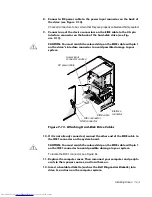
For a drive that comes with its own controller card, connect the other end of the
interface cable to the controller card.
Check all cable connections. Fold cables out of the way to provide airflow for the
fan and cooling vents.
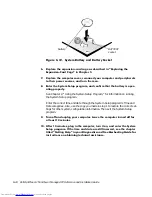
,IWKHLQFKGULYHED\ZDVSUHYLRXVO\HPSW\UHPRYHWKHIURQW
SDQHOLQVHUWIURPWKHIURQWEH]HO
See “Removing and Replacing Front-Panel Inserts” found earlier in this chapter.
diskette/tape drive
interface cable
DC power cable
interface connector
power input connector
Summary of Contents for OptiPlex G1
Page 1: ... ZZZ GHOO FRP HOO 2SWL3OH 0LQL 7RZHU 0DQDJHG 3 6 VWHPV 5 5 1 1 167 7 21 8 ...
Page 8: ...x ...
Page 20: ...xxii ...
Page 34: ...1 14 Dell OptiPlex G1 Mini Tower Managed PC Reference and Installation Guide ...
Page 56: ...2 22 Dell OptiPlex G1 Mini Tower Managed PC Reference and Installation Guide ...
Page 89: ...Working Inside Your Computer 5 9 LJXUH 6 VWHP RDUG XPSHUV jumpered unjumpered ...
Page 128: ...7 16 Dell OptiPlex G1 Mini Tower Managed PC Reference and Installation Guide ...
Page 134: ...A 6 Dell OptiPlex G1 Mini Tower Managed PC Reference and Installation Guide ...
Page 156: ...D 4 Dell OptiPlex G1 Mini Tower Managed PC Reference and Installation Guide ...