


Removing and Replacing Parts on the Mini Tower Chassis
6-3
,QVLGHWKH&RPSXWHU
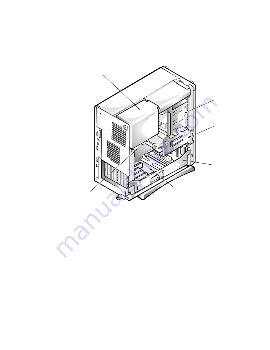
Figure 6-1 shows an internal view of the interior of the mini tower computer
and identifies major components for orientation. Refer to this illustration, as
needed, when performing the component removal/replacement procedures in
this chapter.
)LJXUH,QWHUQDO9LHZRIWKH0LQL7RZHU&RPSXWHU
power supply
system
board
expansion-card
cage
riser board
hard-disk drive
bracket
external drive
bays
Summary of Contents for OptiPlex G1
Page 1: ...ZZZ GHOO FRP HOO 2SWL3OH 0DQDJHG 3 6 VWHPV 6 59 0 18 ...
Page 44: ...1 34 Dell OptiPlex G1 Managed PC Systems Service Manual ...
Page 58: ...3 8 Dell OptiPlex G1 Managed PC Systems Service Manual ...
Page 82: ...4 24 Dell OptiPlex G1 Managed PC Systems Service Manual ...
Page 132: ...6 26 Dell OptiPlex G1 Managed PC Systems Service Manual ...
Page 143: ......


