


Removing and Replacing Parts on the Mini Tower Chassis
6-15
6\VWHP3RZHU6XSSO\
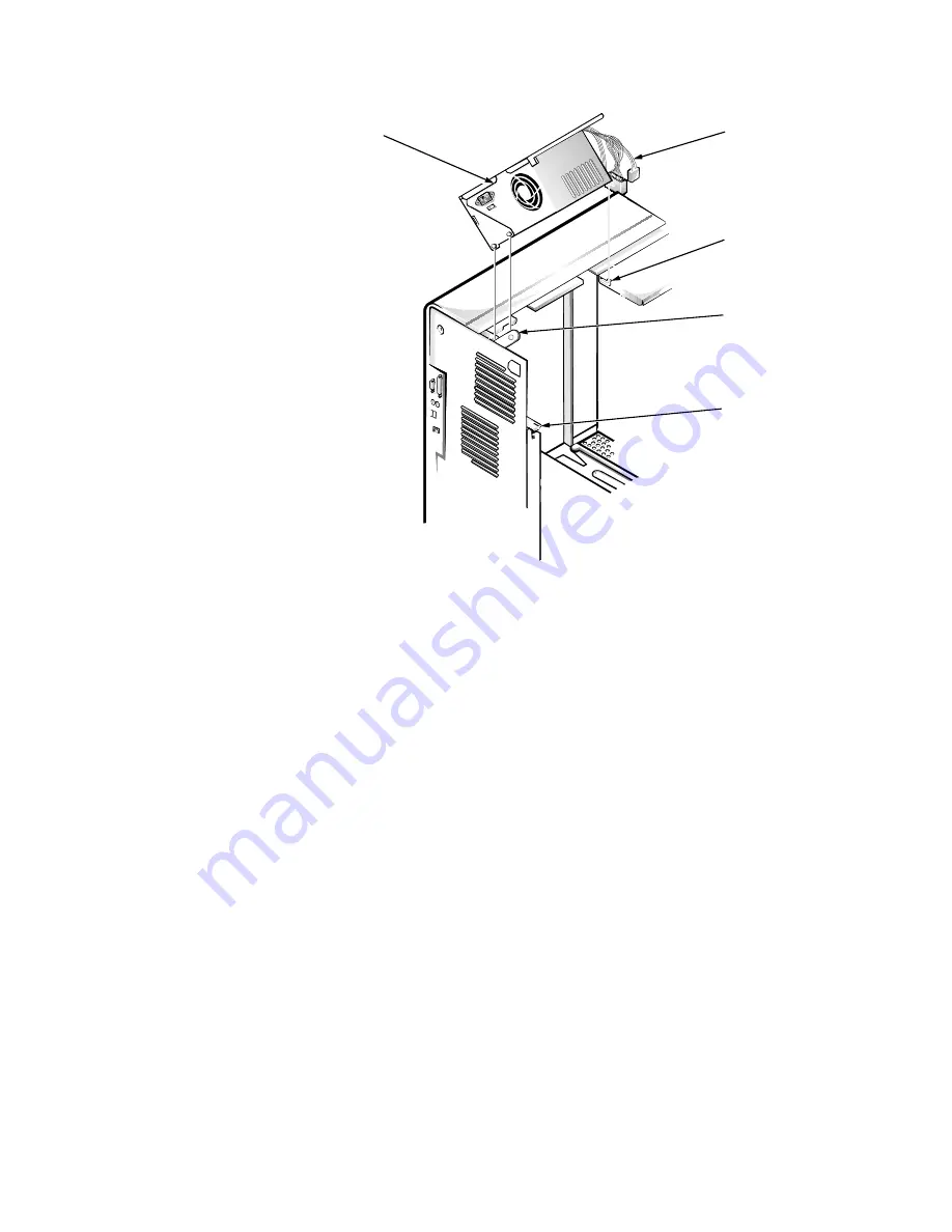
)LJXUH6\VWHP3RZHU6XSSO\5HPRYDO
To remove the system power supply, follow these steps:
'LVFRQQHFWWKH$&SRZHUFDEOHIURPWKHEDFNRIWKHV\VWHPSRZHU
VXSSO\
)UHHWKHV\VWHPSRZHUVXSSO\IURPWKHVHFXULQJWDEODEHOHG
´
5(/($6(
³!
µ
DQGURWDWHLWXSZDUGXQWLOLWORFNV
Press the securing tab to release the power supply.
'LVFRQQHFWWKH'&SRZHUFDEOHVIURPWKHV\VWHPERDUGDQGWKH
GULYHV
)DFLQJWKHOHIWVLGHRIWKHFRPSXWHUPRYHWKHIURQWHQGRIWKHV\V
WHPSRZHUVXSSO\WRZDUG\RXDQGOLIWLWXSWRGLVHQJDJHWKH
SRZHUVXSSO\IURPWKHVORWLQWKHFKDVVLV
/LIWWKHV\VWHPSRZHUVXSSO\IURPWKHFRPSXWHU
When you reinstall the system power supply, place the power-supply detent
link over the pin on the power supply as you position the power supply in the
chassis opening.
DC power cables
power-supply
detent link
power supply
securing tab
slot
Summary of Contents for OptiPlex G1
Page 1: ...ZZZ GHOO FRP HOO 2SWL3OH 0DQDJHG 3 6 VWHPV 6 59 0 18 ...
Page 44: ...1 34 Dell OptiPlex G1 Managed PC Systems Service Manual ...
Page 58: ...3 8 Dell OptiPlex G1 Managed PC Systems Service Manual ...
Page 82: ...4 24 Dell OptiPlex G1 Managed PC Systems Service Manual ...
Page 132: ...6 26 Dell OptiPlex G1 Managed PC Systems Service Manual ...
Page 143: ......


