


System Overview
1-13
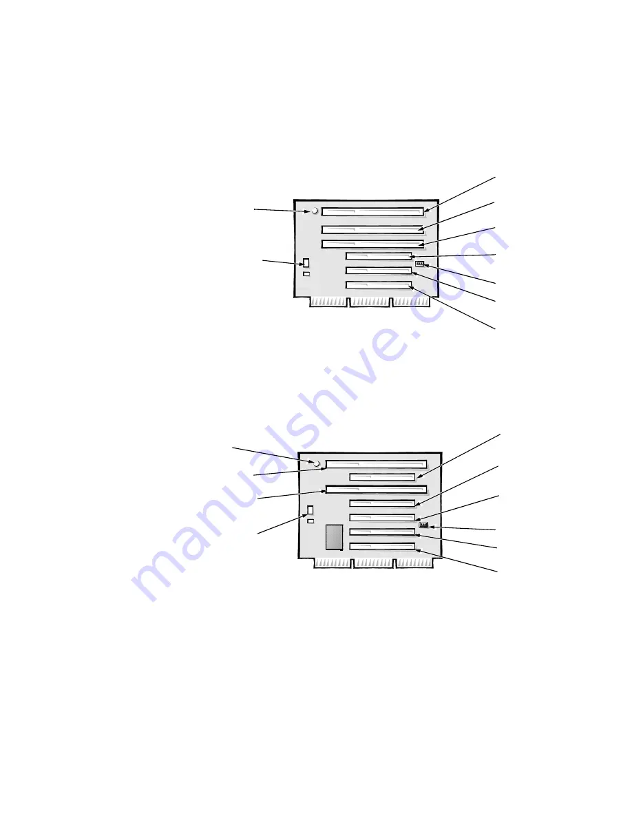
board, with a PCI-to-PCI bridge. Option 2 has two ISA expansion-card connec-
tors and five PCI expansion-card connectors. Two PCI/ISA expansion-card
connector pairs each share an expansion-card slot, again resulting in a total of
five expansion-card slots (see Figure 1-8).
Both riser board options include the P1 connector (for connecting the NIC to
the riser board cable) and an LED. If the LED is on, the riser board is receiving
power; if off, the riser board is not receiving power.
)LJXUH5LVHU%RDUGIRUWKH0LGVL]H&RPSXWHU2SWLRQ
)LJXUH5LVHU%RDUGIRUWKH0LGVL]H&RPSXWHU2SWLRQ
0LQL7RZHU&RPSXWHU·V([SDQVLRQ&DUG6ORWV
The mini tower computers have seven expansion-card slots. The riser board
has four ISA expansion-card connectors and five PCI expansion-card connec-
tors. Two PCI expansion-card connectors share expansion-card slots with two
ISA connectors, resulting in a total of seven expansion-card slots (see
Figure 1-9). The riser board is active, incorporating PCI-to-PCI bridging.
HDLED
connector
ISA3
connector
ISA2
connector
ISA1
connector
PCI3
connector
PCI2
connector
PCI1
connector
P1 connector
LED
ISA1
connector
ISA2
connector
PCI3
connector
PCI2
connector
PCI1
connector
PCI4
connector
PCI5
connector
HDLED
connector
LED
P1 connector
Summary of Contents for OptiPlex G1
Page 1: ...ZZZ GHOO FRP HOO 2SWL3OH 0DQDJHG 3 6 VWHPV 6 59 0 18 ...
Page 44: ...1 34 Dell OptiPlex G1 Managed PC Systems Service Manual ...
Page 58: ...3 8 Dell OptiPlex G1 Managed PC Systems Service Manual ...
Page 82: ...4 24 Dell OptiPlex G1 Managed PC Systems Service Manual ...
Page 132: ...6 26 Dell OptiPlex G1 Managed PC Systems Service Manual ...
Page 143: ......


