


Removing and Replacing Parts on the Low-Profile Chassis
4-11
,QFK'ULYH$VVHPEO\
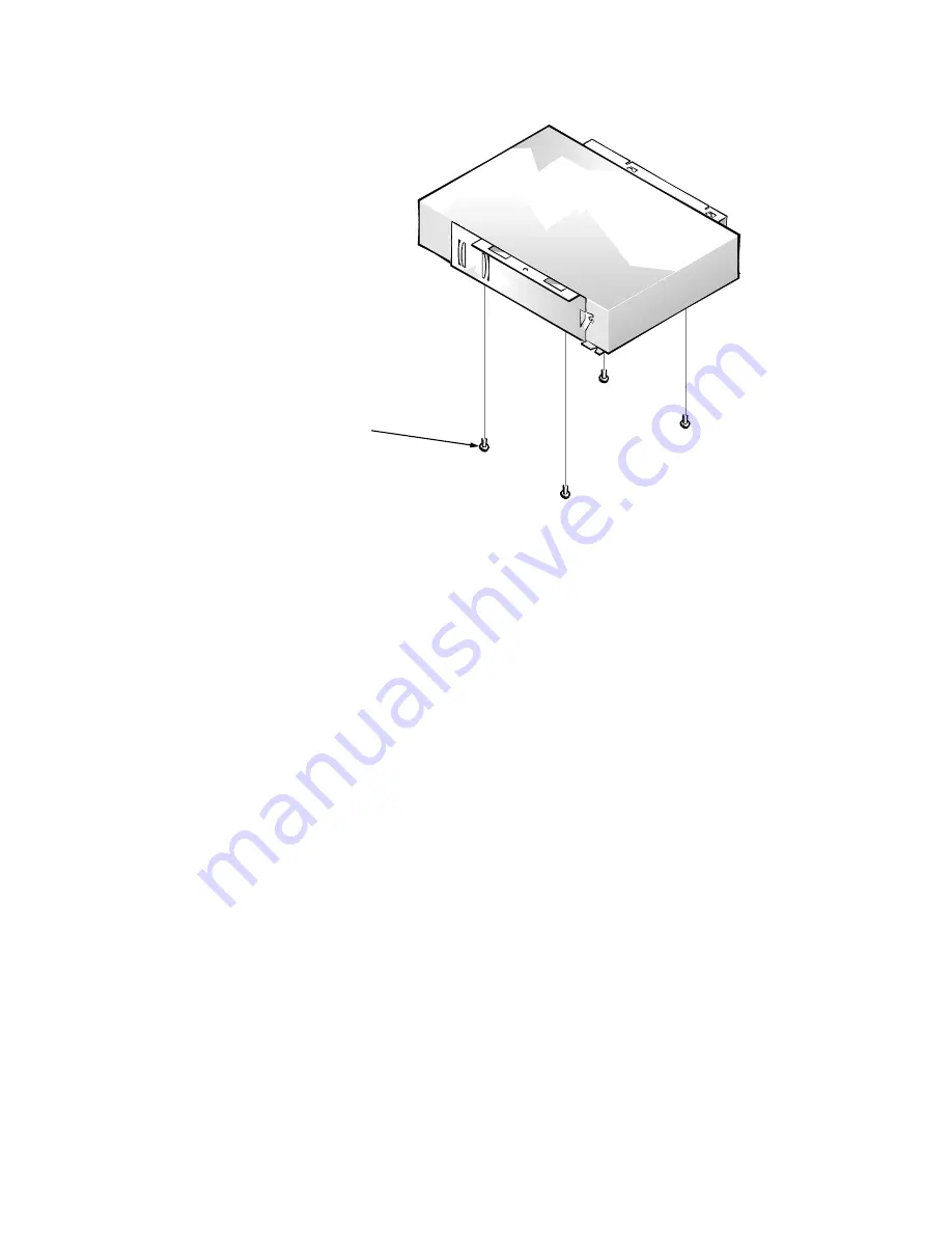
)LJXUH,QFK'ULYH$VVHPEO\5HPRYDO
To remove a 5.25-inch drive assembly, follow these steps:
5HPRYHWKHLQFKGLVNHWWHGULYHDVVHPEO\
'LVFRQQHFWWKH'&SRZHUFDEOHDQGWKHLQWHUIDFHFDEOHIURPWKH
EDFNRIWKHLQFKGULYH
/LIWWKHLQFKGULYHDVVHPEO\VWUDLJKWXSDQGRXWRIWKH
FKDVVLV
/D\WKHLQFKGULYHDVVHPEO\XSVLGHGRZQWKHQUHPRYHWKH
IRXUVFUHZVDWWDFKLQJWKHGULYHWRWKHEUDFNHW
When you replace the 5.25-inch drive, place the front of the drive toward the
front of the bracket; then install the four screws, but do not tighten them. Align
the screws with the score marks on the bracket, and tighten the screws in the
order stamped on the bottom of the bracket.
Check the alignment of the computer cover around the 5.25-inch drive bezel.
Adjust the drive forward or backward on the bracket to align it.
drive-mounting
screws (4)
front of computer
Summary of Contents for OptiPlex G1
Page 1: ...ZZZ GHOO FRP HOO 2SWL3OH 0DQDJHG 3 6 VWHPV 6 59 0 18 ...
Page 44: ...1 34 Dell OptiPlex G1 Managed PC Systems Service Manual ...
Page 58: ...3 8 Dell OptiPlex G1 Managed PC Systems Service Manual ...
Page 82: ...4 24 Dell OptiPlex G1 Managed PC Systems Service Manual ...
Page 132: ...6 26 Dell OptiPlex G1 Managed PC Systems Service Manual ...
Page 143: ......


