


4-18
Dell OptiPlex G1 Managed PC Systems Service Manual
onto its corresponding tab. Push evenly on both sides of the system board as
you slide it into position (do not twist the system board).
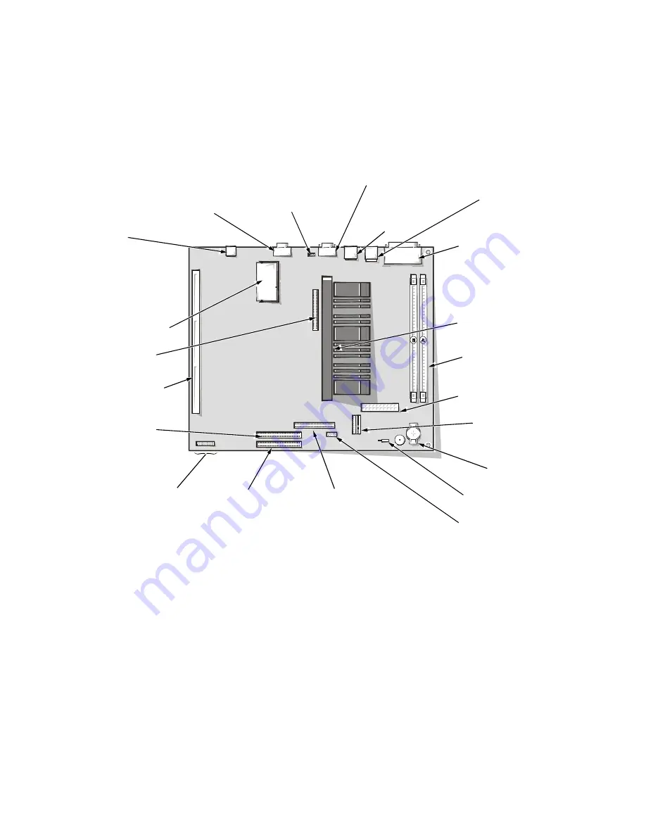
6\VWHP%RDUG&RPSRQHQWV
The subsections that follow Figure 4-16 contain procedures for removing/
replacing system board components.
)LJXUH6\VWHP%RDUG&RPSRQHQWV
',00V
To remove a DIMM from one of the two DIMM sockets, follow these steps:
/RFDWHWKHWZR',00VRFNHWVVHH)LJXUH
7RUHPRYHD',00SXVKRXWZDUGRQWKH',00VRFNHW·VVHFXULQJ
FOLSVXQWLOWKH',00LVUHOHDVHGIURPLWVVRFNHW
SEC cartridge connector
(SLOT1)
primary EIDE
interface connector
(IDE1)
diskette/tape drive
interface connector
(DSKT)
riser board
connector (RISER)
secondary EIDE
interface
connector (IDE2)
system board
jumpers
battery socket
(BATTERY)
control panel
connector (PANEL)
3.3-V power input
connector
(POWER_2)
main power input
connector (POWER_1)
DIMM sockets (2)
(DIMM_A–DIMM_B
front of computer
ATI multimedia
connector (AMC)
video-memory
upgrade socket
(VIDEO_UPGRADE)
optional NIC
connector
(ENET)
video connector
(MONITOR)
microprocessor
fan connector
(FAN)
serial port 2
connector (SERIAL2)
USB connectors (2)
(USB)
parallel/serial port 1
connectors (stacked)
(PARALLEL/SERIAL1)
mouse/keyboard
connectors
(stacked)
(MOUSE/KYBD)
chassis-intrusion switch
connector (INTRUSION)
Summary of Contents for OptiPlex G1
Page 1: ...ZZZ GHOO FRP HOO 2SWL3OH 0DQDJHG 3 6 VWHPV 6 59 0 18 ...
Page 44: ...1 34 Dell OptiPlex G1 Managed PC Systems Service Manual ...
Page 58: ...3 8 Dell OptiPlex G1 Managed PC Systems Service Manual ...
Page 82: ...4 24 Dell OptiPlex G1 Managed PC Systems Service Manual ...
Page 132: ...6 26 Dell OptiPlex G1 Managed PC Systems Service Manual ...
Page 143: ......


