


Removing and Replacing Parts on the Midsize Chassis
5-3
,QVLGHWKH&RPSXWHU
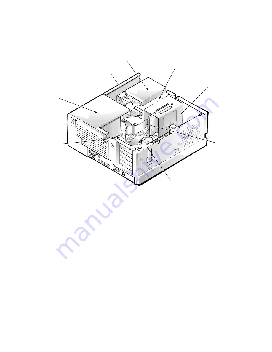
Figure 5-1 shows an internal view of the midsize computer and identifies major
components for orientation. Refer to this illustration, as needed, when per-
forming the component removal/replacement procedures in this chapter.
)LJXUH,QWHUQDO9LHZRIWKH0LGVL]H&RPSXWHU
8VLQJWKH2SWLRQDO6WDQGIRU9HUWLFDO
2ULHQWDWLRQ
Dell offers an optional stand that you can attach to the computer for a mini
tower (vertical) orientation. Although you can attach (and remove) the stand at
any time with a minimum of system disruption, it is easiest to attach before
you set up your computer and connect the back-panel cables.
To attach the stand, follow these steps:
7XUQWKHFRPSXWHURQWRLWVULJKWVLGHVRWKDWWKHGULYHED\VDUHDW
WKHERWWRP
)LWWKHVWDQGRQWRZKDW
ZDV
WKHOHIWVLGHRIWKHFRPSXWHU
Position the stand as shown in Figure 5-2. Align the large round hole in the
stand with the securing button on the side of the cover, and align the cap-
tive thumbscrew in the stand with the screw hole in the cover.
power supply
diskette/tape drive interface cable
hard-disk drive
bracket
hard-disk drive
interface
cable
3.5-inch diskette drive
expansion-card cage
system board
external drive bays
Summary of Contents for OptiPlex G1
Page 1: ...ZZZ GHOO FRP HOO 2SWL3OH 0DQDJHG 3 6 VWHPV 6 59 0 18 ...
Page 44: ...1 34 Dell OptiPlex G1 Managed PC Systems Service Manual ...
Page 58: ...3 8 Dell OptiPlex G1 Managed PC Systems Service Manual ...
Page 82: ...4 24 Dell OptiPlex G1 Managed PC Systems Service Manual ...
Page 132: ...6 26 Dell OptiPlex G1 Managed PC Systems Service Manual ...
Page 143: ......


