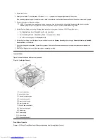
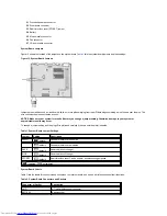
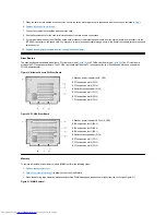
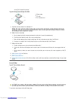
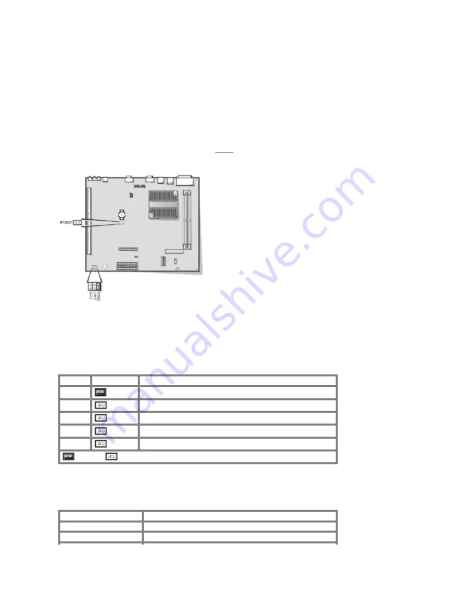
System Board Jumpers
Figure 15 shows the location of the jumpers on the system board.
Table 1
lists the system board jumpers and their settings.
Figure 15. System Board Jumpers
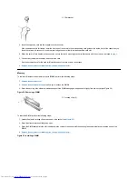
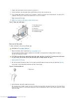
Jumpers are small blocks on a circuit board with two or more pins emerging from them. Plastic plugs containing a wire fit down over the pins. The
wire connects the pins and creates a circuit.
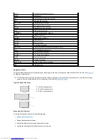
NOTICE: Make sure your system is turned off before you change a jumper setting. Otherwise, damage to your system or
unpredictable results may occur.
To change a jumper setting, pull the plug off its pin(s) and carefully fit it down onto the pin(s) indicated.
Table 1. System-Board Jumper Settings
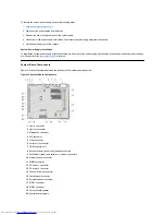
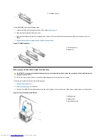
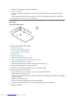
System Board Labels
Table 2 lists the labels for connectors and sockets on your system board, and it gives a brief description of their functions.
Table 2. System Board Connectors and Sockets
21
Diskette/tape-drive connector
22
Riser board connector
23
Real-time clock reset (RTCRST) jumper
24
Battery
25
Modem audio connector
26
Fan connector
27
CD audio cable connector
Jumper
Setting
Description
PSWD
(default)
Password features are enabled.
(default)
Password features are disabled.
SAFE
(default)
Reserved
(do not change).
BIOS
(default)
Reserved
(do not change).
RTCRST
(default)
Real-time clock reset. Can be used for troubleshooting purposes.
jumpered
unjumpered
Connector or Socket
Description
AMC
ATI multimedia channel connector
BATTERY
Battery socket


