


A-2
Dell OptiPlex N Systems Service Manual
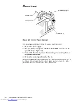
S
ystem Setup Screens
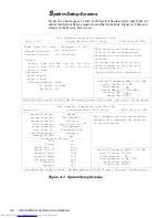
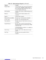
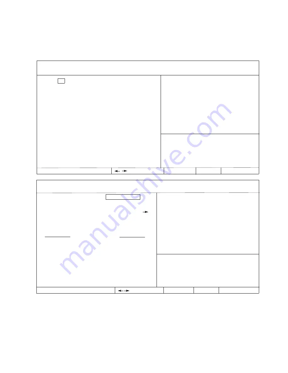
Figure A-1 shows pages 1 and 2 of the System Setup screens, and Table A-1
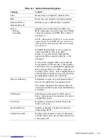
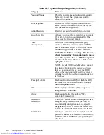
shows the System Setup categories and their functions. Figure A-2 shows a
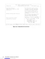
sample of the Device List screen.
Figure A-1. System Setup Screens
Report
Not Enabled
Unlocked
Device List, Ctrl
Not Enabled
Disabled 00:00
Disabled
Off
Not Installed
Integrated Devices
Dell Computer Corporation (www.dell.com)
Page 2 of 2
System OptiPlex N 5233 Setup
BIOS Version:
XXX
Drives:
Primary Type Cyls Hds Pre LZ Sec Size
Drive 0: Auto 1023 64 -1 1023 63 2111
Drive 1: None
Level 2 Cache:
Video Memory:
System Memory:
Service Tag:
Asset Tag:
Esc exit
change values
Alt-B reboot
Diskette Drive B:
Dell Computer Corporation (www.dell.com)
Page 1 of 2
Date: Tue August 26, 1997
System OptiPlex N 5233 Setup
Diskette Drive A:
Tab,Shift-Tab change fields
Secondary
Drive 0:None
Drive 1:None
Not Installed
change values
Esc exit
This category sets the time in
24-hour format (hours:minutes:
seconds) for the internal clock/
calendar.
To change the value in a field,
enter a number or use the left-
or right-arrow key.
Changes take effect immediately.
BIOS Version:
XXX
This category sets whether keyboard-
related error messages are reported
at system startup.
Alt-P next
Tab,Shift-Tab change fields
Time: 13:17:02
Alt-P next
Alt-B reboot
Reserved Memory:
CPU Speed:
Num Lock:
None
233 MHz
On
Keyboard Errors:
System Password:
Password Status:
Boot Sequence:
Setup Password:
Auto Power On:
Power Management:
Wakeup On LAN:
On
On
Auto
Auto
378h
PS/2
Auto
Off
On
NIC:
Mouse:
Serial Port 1:
Serial Port 2:
Parallel Port:
Parallel Mode:
IDE Hard Disk:
Diskette:
Speaker:
512 KB
2 MB
32 MB (EDO)
XXXXX
XXXXX
Level 2 Cache:
Video Memory:
System Memory:
Service Tag:
Asset Tag:
512 KB
2 MB
32 MB (EDO)
XXXXX
XXXXX
Pentium
®
Processor/MMX ™ - 233 MHz
Pentium
®
Processor/MMX ™ - 233 MHz


